Advertisement
Quick Links
CAT4106AGEVB
CAT4106 LED Driver
Evaluation Board
User's Manual
Introduction
This
document
describes
evaluation board for the CAT4106 quad-channel DC/DC
boost LED driver. The major operating characteristics of the
CAT4106 can be measured with this board.
The CAT4106 DC/DC converter is capable of driving up
to 4 strings of LEDs with tight matching. This device is
designed to drive LED strings up to 36 V. The LED
brightness is set by a single resistor from the RSET pin to
GND and PWM dimming is available via the EN/PWM pin.
Additional information can be found in the CAT4106 data
sheet.
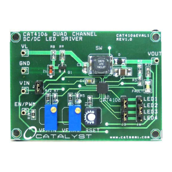
Figure 1. CAT4106AGEVB Board
© Semiconductor Components Industries, LLC, 2011
October, 2011 − Rev. 1
the
CAT4106AGEVB
1
http://onsemi.com
EVAL BOARD USER'S MANUAL
Operation Procedure
The CAT4106AGEVB board contains one CAT4106 in
a typical application circuit. The board can be powered in
two different ways. With the J1 jumper in place a single high
voltage supply (6 V to 24 V) can be applied between VL and
GND. A circuit on board will generate a lower, regulated
voltage for the VIN pin (6.2 V – V
can also be powered separately by removing the J1 jumper
and applying a second voltage to the VIN test point. The
voltage at VIN should not exceed 6.0 V.
VFMAX and VFMIN are set by potentiometers R4 and
R6 respectively. The VFMIN potentiometer is located
closest to the VIN test point. These can be used to set the
maximum and minimum allowable forward voltages for any
given LED string. For the CAT4106AGEVB, the settings for
these potentiometers are calculated as follows:
V
FMAX
R4 + 69.8 kW
1.2 V
V
FMIN
R6 + 60 kW
* 1 * 100 kW
1.2 V
Any open LED conditions will trigger a fault condition.
Any short LED conditions will only trigger a fault condition
during power-up. A red LED will turn on when a fault
condition takes place.
The LED current is set by potentiometer R13 which is
labeled RSET on the CAT4106AGEVB. The anode end of
each LED string should be connected to VOUT and the
cathode ends can be connected at the available header
connectors J5 and J6. Placing jumpers on J5 and J6 headers
allows to short two or more LED channels together.
EN or PWM input signals can be connected at the
EN/PWM test point. The voltage at EN/PWM should not
exceed 6.0 V. The CAT4106 can support PWM frequencies
up to 2 kHz.
of transistor M1). VIN
GS
* 1 * 100 kW
(eq. 1)
(eq. 2)
Publication Order Number:
EVBUM2024/D
Advertisement

Related Manuals for ON Semiconductor CAT4106


Summary of Contents for ON Semiconductor CAT4106
- Page 1 CAT4106 can be measured with this board. voltage supply (6 V to 24 V) can be applied between VL and The CAT4106 DC/DC converter is capable of driving up GND. A circuit on board will generate a lower, regulated to 4 strings of LEDs with tight matching. This device is voltage for the VIN pin (6.2 V –...
- Page 2 649 W LED3 LED3 LED4 69.8 kW 60 kW 6.2 V LED4 FAULT FAULT PGND 20 kW 28 kW CAT4106 LED1 LED1 FAULT LED2 1 kW LED2 LED3 LED3 LED4 LED4 Figure 2. CAT4106AGEVB Board Schematic Table 1. BILL OF MATERIALS...
- Page 3 LIMITATIONS OF LIABILITY: ON Semiconductor shall not be liable for any special, consequential, incidental, indirect or punitive damages, including, but not limited to the costs of requalification, delay, loss of profits or goodwill, arising out of or in connection with the board, even if ON Semiconductor is advised of the possibility of such damages. In no event shall ON Semiconductor’s aggregate liability from any obligation arising out of or in connection with the board, under any theory of liability, exceed the purchase price paid for the board, if any.
Need help?
Do you have a question about the CAT4106 and is the answer not in the manual?
Questions and answers