Advertisement
Quick Links
CAT4201AGEVB
CAT4201 LED Driver
Evaluation Board
User's Manual
Introduction
This
document
describes
evaluation board for the CAT4201 high efficiency
step-down LED driver. Boards equipped with a 9 V battery
and separate LED module can be used for demonstrations
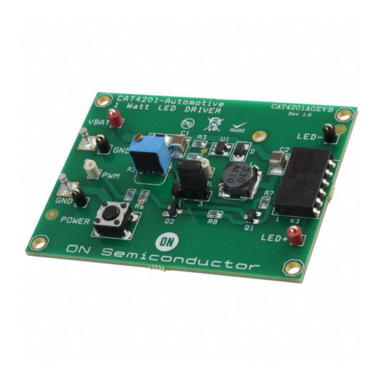
(see Figure 1).
The CAT4201 is a high efficiency step-down LED driver
from Catalyst Semiconductor. This device is designed to
drive high brightness LEDs up to 350 mA from a power
supply up to 28 V. The LED brightness is controlled by a
single resistor from the RSET pin to GND. Analog dimming
and idle mode control are available through the CTRL input.
An external circuit is provided on the CAT4201AGEVB for
PWM dimming.
Operation Procedure
The CAT4201AGEVB board has two modes of operation.
The first is normal operation and the second is operation
with PWM dimming. Normal operation is set by placing
jumper J1 in the right side position with pins 2 and 3 tied
together. In this mode, the CTRL pin is pulled up to the LED
cathode (LED−). The LED(s) will be at full brightness as
© Semiconductor Components Industries, LLC, 2013
July, 2013 − Rev. 1
the
CAT4201AGEVB
Figure 1. CAT4201AGEVB with LED Module
1
http://onsemi.com
EVAL BOARD USER'S MANUAL
long as the CTRL pin is greater than 3 V. LED current can
be set from 70 mA to 350 mA by adjusting potentiometer
R2.
To set the board for PWM dimming, jumper J1 should be
placed in the left side position with pins 1 and 2 tied together.
A PWM signal can be applied to the PWM pin to dim the
LED brightness. The amplitude of the PWM signal should
be greater than 1 V.
Device Demonstration
To set up the CAT4201AGEVB for demonstrations, the
board should be configured for normal operation with a 9 V
battery securely placed in the holder. A separate LED
module should also be plugged into the 6-pin connector, as
shown in Figure 1. To turn on the LED, press and hold the
POWER button. The LED will turn off once the button is
released.
Publication Order Number:
EVBUM2205/D
Advertisement

Related Manuals for ON Semiconductor CAT4201AGEVB


Summary of Contents for ON Semiconductor CAT4201AGEVB
- Page 1 A PWM signal can be applied to the PWM pin to dim the and idle mode control are available through the CTRL input. LED brightness. The amplitude of the PWM signal should An external circuit is provided on the CAT4201AGEVB for be greater than 1 V. PWM dimming.
- Page 2 CAT4201AGEVB SCHEMATIC Figure 2. CAT4201AGEVB Schematic http://onsemi.com...
- Page 3 CAT4201AGEVB TEST PROCEDURE FOR THE CAT4201AGEVB EVALUATION BOARD Introduction Test Set-up This document describes the test procedure for the The CAT4201 evaluation board must have the jumper J1 CAT4201 evaluation board. The test procedure must be installed between pins 2 and 3 (right position).
- Page 4 CAT4201AGEVB Table 1. CAT4201AGEVB BILL OF MATERIALS Name Qty. Description Manufacturer Part Number High Efficiency Step-down LED Driver, SOT−23−5 ON Semiconductor CAT4201 PNP Bipolar Transistor −45 V/−500 mA, SOT−23 ON Semiconductor BC807-25LT1G NPN Bipolar Transistor 45 V/100 mA, SOT−23 ON Semiconductor BC847CLT1G Schottky Diode 40 V/500 mA, Size SOD−323...
- Page 5 onsemi, , and other names, marks, and brands are registered and/or common law trademarks of Semiconductor Components Industries, LLC dba “onsemi” or its affiliates and/or subsidiaries in the United States and/or other countries. onsemi owns the rights to a number of patents, trademarks, copyrights, trade secrets, and other intellectual property. A listing of onsemi’s product/patent coverage may be accessed at www.onsemi.com/site/pdf/Patent−Marking.pdf.
Need help?
Do you have a question about the CAT4201AGEVB and is the answer not in the manual?
Questions and answers