
Subscribe to Our Youtube Channel
Related Manuals for Moffat Blue Seal Evolution GT18

Summary of Contents for Moffat Blue Seal Evolution GT18
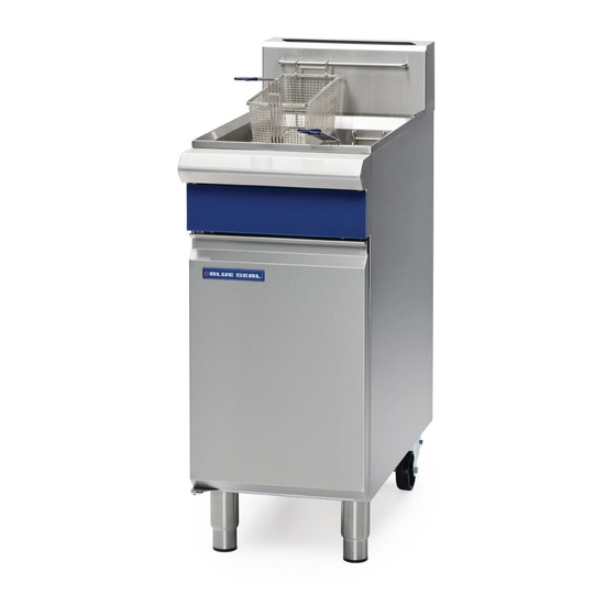
- Page 1 4 0 0 m m G a s F r y e r M o d e l G T 1 8 I N S T A L L A T I O N A N D O P E R A T I O N M A N U A L 236863-4...
- Page 2 The reproduction or copying of any part of this manual by any means whatsoever is strictly forbidden unless authorized previously in writing by the manufacturer. In line with policy to continually develop and improve its products, Moffat Ltd. reserves the right to change the specifications and design without prior notice.
-
Page 3: Table Of Contents
Contents List BLUE SEAL GT18 - 400mm GAS FRYER (Single Tank - 18 Ltr) Part 1 Introduction..................2 Part 2 Specifications .................. 3 General ............................3 Gas Connection ......................... 3 Gas Supply Requirements ......................4 Part 3 Installation ..................4 Installation Requirements ...................... -
Page 4: Part 1 Introduction
Part 1 Introduction We are confident that you will be delighted with your Blue Seal 400mm Gas Fryer, and it will become a most valued appliance in your commercial kitchen. To ensure you receive the utmost benefit from your new Blue Seal Appliance, there are two important things you can do. -
Page 5: Part 2 Specifications
Part 2 Specifications Model Covered in this Specification - Gas Connection GT18 400mm GAS FRYER (Single Tank - 18 Ltr). Gas supply connection point is located 40mm from the right hand side, 24mm from the rear and 223mm from the floor. - Flexible Hose Connection If a Gas Hose assembly is used to connect this appliance, the hose and all fittings must have a... -
Page 6: Gas Supply Requirements
Part 2 Specifications Gas Supply Requirements - Non UK Models: Gas Natural LP Gas / Butane Town Gas (**) Input Rating 90 MJ/hr 90 MJ/hr 90 MJ/hr (N.H.G.C.) (85,300 Btu/hr) (85,300 Btu/hr) (85,300 Btu/hr) 1.13 - 2.0 kPa 2.75 - 3.0 kPa 0.75 - 1.5 kPa Supply Pressure (4.5”... -
Page 7: Part 3 Installation
Part 3 Installation Installation Requirements Location NOTE: 1. This appliance must be installed in a suitably It is most important that this appliance is installed ventilated room to prevent dangerous build up correctly and that operation is correct before use. of combustion products. -
Page 8: Assembly
Part 3 Installation Assembly 4. Locate the appliance into its final operating position and using a spirit level, adjust the legs so that the unit is level and at the correct height. This model is delivered completely assembled. Ensure that the legs are securely attached. 5. -
Page 9: Commissioning
Part 3 Installation Commissioning The following commissioning checks must be carried out before the fryer is handed over for use, to ensure that the unit operates correctly and the operator(s) understand correct operating procedure. 1. Before leaving the new installation; WARNING: O NOT USE A NAKED FLAME TO CHECK FOR GAS LEAKAGES a. -
Page 10: Part 4 Operation
Part 4 Operation AUTI ON This appliance is for professional use and is only to be used by qualified persons. Only qualified service persons are to carry out installation, servicing or gas conversion operations. Components having adjustments protected (e.g. paint sealed) by the manufacturer should not be adjusted by the user / operator. -
Page 11: Before Use
Part 4 Operation WARNING: GREAT CARE MUST BE TAKEN BY THE OPERATOR TO USE THE FRYER SAFELY TO GUARD AGAINST THE RISK OF FIRE. DO NOT LEAVE THE FRYER UNATTENDED DURING OPERATION DO NOT HOT. REPLENISH THE OIL FRYING MEDIUM IN THE FRYER WHEN THE FRYER IS ... -
Page 12: Lighting The Main Burner
Part 4 Operation Lighting the Main Burner and Fats. 1. Ensure pilot burner is alight, by visually checking 1. Prepare the food correctly. Prepare food in as through the Pilot Burner Viewing Opening. nearly uniform pieces as possible and bring the food up to room temperature. -
Page 13: Part 5 Cleaning And Maintenance
Part 5 Cleaning and Maintenance General Draining and Cleaning Opening the Drain Valve WARNING: a. Lift the locking slide on valve handle (Fig 1) to release valve. DO NOT USE FLAMMIBLE SOLVENTS AND CLEANING AIDS ON b. While holding the locking slide in the OR IN CLOSE PROXIMITY TO THE FRYER WHILST THE FRYER IS STILL withdrawn position, rotate the handle HOT. -
Page 14: Weekly Cleaning
Part 5 Cleaning and Maintenance 4. Carefully open the drain valve to minimise 6. Empty the fryer and rinse thoroughly with water. splashing, and take care not to overfill the Use a 1 part vinegar to 15 parts water solution to container. -
Page 15: Part 6 Gas Conversion
Part 6 Gas Conversion Gas Conversion Procedure 5. Cut and remove any Disconnect Gas Cut Tie Connection cable ties as required Wraps 6. Disconnect the flexi AUTI ON tube gas connection at the top of the Gas Ensure that the Unit is isolated from the gas Control Valve. - Page 16 Part 6 Gas Conversion Main Burner Injectors Town Gas Only NOTE: 1. To remove Main For Town Gas application, Gas Control Valve - Burner Injectors (Qty Injector Operating Pressure Adjusting Screw should be 9), use a ⅝” A/F replaced with the Knock Out Plug supplied in Town spanner to prevent Gas Kit and the operating pressure adjusted at the the Injector Mounting...
-
Page 17: Gas Specifications
Part 6 Gas Conversion Gas Specifications - Australia: Natural Gas LP Gas (Propane) Main Burner Injectors Ø 1.55mm Ø 0.95mm Pilot Burner Injectors 0.62 0.35 Pilot Screw Adjustment Full Out (CCW) 1½ turns out (CCW) 0.90 kPa (*) 2.50 kPa (*) Burner Operating Pressure (9.0 mbar) (25 mbar) -
Page 18: Part 7 Replacement Parts List
Part 7 Replacement Parts List Replacement Parts List IMPORTANT: Only genuine qualified replacement parts should be used for the servicing and repair of this appliance. The instructions supplied with the parts should be followed when replacing components. For further information and servicing instructions, contact your nearest qualified service branch (contact details are as shown on the reverse of the front cover of this manual).
Need help?
Do you have a question about the Blue Seal Evolution GT18 and is the answer not in the manual?
Questions and answers
What is the UK part number for the GT18 fryer?
The UK part number for the Moffat Blue Seal Evolution GT18 fryer is 236863-4.
This answer is automatically generated
What is the UK PART NUMBER for the GT18 fryer.
The UK part number for the Moffat Blue Seal Evolution GT18 fryer is 236863-4.
This answer is automatically generated