Table of Contents
Advertisement
Quick Links
Advertisement
Table of Contents

Subscribe to Our Youtube Channel
Related Manuals for Rohde & Schwarz TS-PSM4


Summary of Contents for Rohde & Schwarz TS-PSM4
- Page 1 ® R&S TS-PSM4 High-Power Switch Module User Manual (;ÜKî2) 1178.2796.02 ─ 01...
- Page 2 Rohde & Schwarz GmbH & Co. KG. Trade names are trademarks of the owners. ® ® The following abbreviations are used throughout this manual: R&S TS-PSM4 is abbreviated as R&S TS-PSM4 and R&S TS-PRIO2 as R&S TS-PRIO2.
-
Page 3: Basic Safety Instructions
Basic Safety Instructions Always read through and comply with the following safety instructions! All plants and locations of the Rohde & Schwarz group of companies make every effort to keep the safety standards of our products up to date and to offer our customers the highest possible degree of safety. Our products and the auxiliary equipment they require are designed, built and tested in accordance with the safety standards that apply in each case. - Page 4 Basic Safety Instructions Symbol Meaning Symbol Meaning Caution ! Hot surface Alternating current (AC) Protective conductor terminal Direct/alternating current (DC/AC) To identify any terminal which is intended for connection to an external conductor for protection against electric shock in case of a fault, or the terminal of a protective earth Earth (Ground) Class II Equipment...
- Page 5 Basic Safety Instructions Operating states and operating positions The product may be operated only under the operating conditions and in the positions specified by the manufacturer, without the product's ventilation being obstructed. If the manufacturer's specifications are not observed, this can result in electric shock, fire and/or serious personal injury or death. Applicable local or national safety regulations and rules for the prevention of accidents must be observed in all work performed.
- Page 6 Basic Safety Instructions 6. The product may be operated only from TN/TT supply networks fuse-protected with max. 16 A (higher fuse only after consulting with the Rohde & Schwarz group of companies). 7. Do not insert the plug into sockets that are dusty or dirty. Insert the plug firmly and all the way into the socket provided for this purpose.
- Page 7 Basic Safety Instructions 2. Before you move or transport the product, read and observe the section titled "Transport". 3. As with all industrially manufactured goods, the use of substances that induce an allergic reaction (allergens) such as nickel cannot be generally excluded. If you develop an allergic reaction (such as a skin rash, frequent sneezing, red eyes or respiratory difficulties) when using a Rohde &...
- Page 8 Basic Safety Instructions 2. Adjustments, replacement of parts, maintenance and repair may be performed only by electrical experts authorized by Rohde & Schwarz. Only original parts may be used for replacing parts relevant to safety (e.g. power switches, power transformers, fuses). A safety test must always be performed after parts relevant to safety have been replaced (visual inspection, protective conductor test, insulation resistance measurement, leakage current measurement, functional test).
- Page 9 Instrucciones de seguridad elementales Waste disposal/Environmental protection 1. Specially marked equipment has a battery or accumulator that must not be disposed of with unsorted municipal waste, but must be collected separately. It may only be disposed of at a suitable collection point or via a Rohde &...
- Page 10 Instrucciones de seguridad elementales Se parte del uso correcto del producto para los fines definidos si el producto es utilizado conforme a las indicaciones de la correspondiente documentación del producto y dentro del margen de rendimiento definido (ver hoja de datos, documentación, informaciones de seguridad que siguen). El uso del producto hace necesarios conocimientos técnicos y ciertos conocimientos del idioma inglés.
- Page 11 Instrucciones de seguridad elementales Símbolo Significado Símbolo Significado Aviso: Cuidado en el manejo de dispositivos Distintivo de la UE para la eliminación por sensibles a la electrostática (ESD) separado de dispositivos eléctricos y electrónicos Más información en la sección "Eliminación/protección del medio ambiente", punto 2.
- Page 12 Instrucciones de seguridad elementales 1. Si no se convino de otra manera, es para los productos Rohde & Schwarz válido lo que sigue: como posición de funcionamiento se define por principio la posición con el suelo de la caja para abajo, modo de protección IP 2X, uso solamente en estancias interiores, utilización hasta 2000 m sobre el nivel del mar, transporte hasta 4500 m sobre el nivel del mar.
- Page 13 Instrucciones de seguridad elementales 6. Solamente está permitido el funcionamiento en redes de alimentación TN/TT aseguradas con fusibles de 16 A como máximo (utilización de fusibles de mayor amperaje solo previa consulta con el grupo de empresas Rohde & Schwarz). 7.
- Page 14 Instrucciones de seguridad elementales Funcionamiento 1. El uso del producto requiere instrucciones especiales y una alta concentración durante el manejo. Debe asegurarse que las personas que manejen el producto estén a la altura de los requerimientos necesarios en cuanto a aptitudes físicas, psíquicas y emocionales, ya que de otra manera no se pueden excluir lesiones o daños de objetos.
- Page 15 Instrucciones de seguridad elementales Reparación y mantenimiento 1. El producto solamente debe ser abierto por personal especializado con autorización para ello. Antes de manipular el producto o abrirlo, es obligatorio desconectarlo de la tensión de alimentación, para evitar toda posibilidad de choque eléctrico. 2.
- Page 16 Instrucciones de seguridad elementales 2. Las asas instaladas en los productos sirven solamente de ayuda para el transporte del producto por personas. Por eso no está permitido utilizar las asas para la sujeción en o sobre medios de transporte como p. ej. grúas, carretillas elevadoras de horquilla, carros etc. Es responsabilidad suya fijar los productos de manera segura a los medios de transporte o elevación.
- Page 17 Quality management Certified Quality System ISO 9001 and environmental Certified Environmental System management ISO 14001 Sehr geehrter Kunde, Dear customer, Cher client, Sie haben sich für den Kauf You have decided to buy a Vous avez choisi d’acheter un eines Rohde & Schwarz Produk- Rohde &...
-
Page 18: Customer Support
Customer Support Technical support – where and when you need it For quick, expert help with any Rohde & Schwarz equipment, contact one of our Customer Support Centers. A team of highly qualified engineers provides telephone support and will work with you to find a solution to your query on any aspect of the operation, programming or applications of Rohde &... -
Page 19: Safety Advice
The R&S CompactTSVP and R&S PowerTSVP test platforms are principally designed for operating voltages up to 125 V. The R&S TS-PSM4 is suitable for voltages of up to +30 VDC and must only be used correspondingly. When higher currents are run through, relays and circuit board can become very hot. - Page 20 PXI modules, must be specified for this voltage. 1.3 Characteristics Table 1-1: Characteristics R&S TS-PSM4 Characteristics R&S TS-PSM4 Deployable in the R&S TS-PCA3 (R&S CompactTSVP) and R&S TS-PWA3 (R&S PowerTSVP) chassis Control via CAN bus...
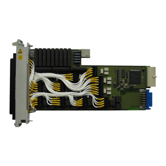
- Page 21 R&S TS-PSM4 2 View Figure 2-1 shows the view of the High-power Switch Module R&S TS-PSM4 (variant 03). Figure 2-1: View of the R&S TS-PSM4 (variant 03) Figure 2-2 shows the view of the High-power Switch Module R&S TS-PSM4B (variant 02).
-
Page 22: Block Diagram
® Block diagram R&S TS-PSM4 3 Block diagram Figure 3-1 shows the block diagram of the High-power Switch Module R&S TS-PSM4. Figure 3-1: Block diagram R&S TS-PSM4 User Manual 1178.2796.02 ─ 01... -
Page 23: Mechanical Construction
FRAM are attached. The connector X10 (only R&S TS-PSM4 (variant 03)) is located on the front side of the module. The R&S TS-PSM4B (variant 02)) in contrast is supplied without this connec- tor. - Page 24 Figure 4-2: R&S TS-PSM4 Rear ( to backplane of the chassis) In contrast to the R&S TS-PSM4B (variant 02) the cabling of the connector (VPC) mounted on the front of the R&S TS-PSM4 (variant 03) with the appropriate terminals on the base board has already been done.
- Page 25 ® Construction R&S TS-PSM4 R&S TS-PSM4 Figure 4-3: R&S TS-PSM4 (variant 03) Base board Figure 4-4: R&S TS-PSM4B (variant 02) Base board User Manual 1178.2796.02 ─ 01...
-
Page 26: Display Elements
Table 4-2: Display elements on the R&S TS-PSM4 Beschreibung Fault condition: (red) Lights up when a fault is detected on the R&S TS-PSM4 in the power-on test after the supply voltage is switched on. Communication: (yellow) Lights up briefly when the R&S TS-PSM4 is accessed via the interface. - Page 27 4.2.1 Mechanical construction The R&S TS-PRIO2 Rear-I/O-Module consists of a board which holds the connectors X20 and X11 (to the R&S TS-PSM4) on the backplane side. Figure 4-5: R&S TS-PRIO2 backplane side (to the R&S TS-PSM4) The connectors X1 to X5 are located on the side accessible to the user (rear of the R&S TS-PWA3).
- Page 28 ® Construction R&S TS-PSM4 R&S TS-PRIO2 Figure 4-6: R&S TS-PRIO2 contact side (rear of R&S TS-PWA3 chassis) For more information about the connectors X1 to X5 may be obtained from the manu- facturer PHOENIX CONTACT. The name of the connector X1 and X2 is: PTSM 0.5/ 4-2.5-H THR R32 - 1770908...
- Page 29 TS-PWA3 chassis, the 16 A high current channels 9 to 20 and all 2 A channels of the R&S TS-PSM4 on the rear of the chassis will be made accessible via the connectors X3 and X4. For this purpose the R&S TS-PSM4 module must be installed in slot 16 in the chassis.
- Page 30 Construction R&S TS-PSM4 R&S TS-PK04 Figure 4-8: Installation of R&S TS-PSM4 with R&S TS-PK04 in the CompactTSVP R&S TS-PCA3 4.3.1 Mechanical construction Figure 4-9 the installation of the R&S TS-PK04 cable set in the CompactTSVP R&S TS-PCA3 (cTSVP) and its connections to the R&S TS-PSM4 (here shown in simplified form) is displayed.
- Page 31 Table 4-4: Connectors on R&S TS-PK04 cable set Abbreviation Interface of high power channels 9 to 20 with the R&S TS-PSM4. X3 und X4 Interface of the high power channels 9 to 20 and low power channels 1 to 8 with the load or voltage source.
-
Page 32: Functional Description
6) 5.1.1 Signal concept The power relays of all channels of the R&S TS-PSM4 can be wired up with power supplies or loads via the front of the module. In addition all channels can be routed to the rear of the R&S TS-PWA3 PowerTSVP chassis via the optional R&S TS-PRIO2 Rear-I/O-Module. -
Page 33: Application Examples
(Figure 5-1) the voltage supply is connected to the COM lines on the rear of the R&S TS-PSM4 . This can be done via the R&S TS-PRIO2 optionally installed in the R&S TS-PWA3 or the R&S TS-PK04 cable set in the TS-PCA3 chassis. The load is connected to the NO lines located on the front of the R&S TS-PSM4 . - Page 34 Via the rspsm4_GetCalculatedCurrent function of the IVI soft- ware driver that is part of the R&S TS-PSM4, the current belonging to this voltage level can be retrieved. It is calculated via correction values stored on the module. See also the programming example later on in this document.
- Page 35 ® Functional description R&S TS-PSM4 R&S TS-PSM4 Figure 5-2: Application example - current measurement with load in standby mode User Manual 1178.2796.02 ─ 01...
- Page 36 6 Setting up 6.1 Channel wiring of the R&S TS-PSM4B (variant 02) In contrast to the completely cabled R&S TS-PSM4 (variant 03) with mounted VPC connector, the R&S TS-PSM4B (variant 02) is supplied without channel wiring and with simple front plate. In this version the user can himself carry out the wiring of the chan- nels that he needs.
- Page 37 ® Setting up R&S TS-PSM4 Channel wiring of the R&S TS-PSM4B (variant 02) Figure 6-2: Opening the terminal contact CH16_COM Figure 6-3: Over the upper opening of the terminal the metal spring can be pressed down The wire to be mounted is now inserted into the exposed lower opening. To establish a good connection the wire must be free of its insulation by a length of about 6 mm.
- Page 38 Channel wiring of the R&S TS-PSM4B (variant 02) Figure 6-4: The wire can be mounted in the lower round opening As an example of a complete wiring here the wiring of the R&S TS-PSM4 (variant 03) is shown: Figure 6-5: R&S TS-PSM4 (variant 03) In the identical terminals of the high-power and low-power channels of the R&S TS-...
- Page 39 4. Insert the R&S TS-PSM4 with moderate pressure 5. The top pilot pin of the R&S TS-PSM4 must be guided into the right-hand hole, the bottom one into the left-hand hole on the CompactTSVP housing. 6. The R&S TS-PSM4 is correctly inserted if a definite stop can be felt.
- Page 40 PowerTSVP R&S TS-PWA3 can be made accessible. If the R&S TS-PSM4 is operated in slot 16, there is the capability for both CompactTSVP R&S TS-PCA3 and PowerTSVP R&S TS-PWA3 to run all low power and high power channels 9 to 20 to the X3 and X4 connectors on the rear of the unit via the optional R&S TS-PK04 cable set.
- Page 41 2. Select an appropriate rear slot. The R&S TS-PRIO2 requires one slot. See also "PowerTSVP operating manual", section "Permissible module configura- tions" . 3. Select an appropriate Rear-I/O-Slot to the R&S TS-PSM4. 4. Loosen the screws and remove the appropriate front plate section from the Pow- erTSVP chassis.
-
Page 42: Driver Software
To use the driver, the IVI and VISA libraries from National Instruments are necessary. 7.2 Softpanel The software package of the R&S TS-PSM4 includes a so-called softpanel. The soft- panel enables interactive operation of the module. User Manual 1178.2796.02 ─ 01... - Page 43 ® Software R&S TS-PSM4 Softpanel Figure 7-1: Softpanel R&S TS-PSM4 User Manual 1178.2796.02 ─ 01...
- Page 44 CH10_COM at the rear of the module TS-PSM4 and the load is connected to CH9_NO and CH10_NO at the front of the module. The sense-lines of the power supply are routed to the load via TS-PSM4 channels 1 and 2. The current through channel 10 is determined indirectly by measuring the voltage at the 5 mOhms shunt resistor of channel 10.
- Page 45 ® Software R&S TS-PSM4 Programming with GTSL Libraries first TS-PSAM module, because it is already tested in the basic self test. ; SFTDll = sftmpsam.dll ; SFTPrefix = SFTMPSAM ; Analog bus pseudo-device, used by ROUTE, SWMGR and EGTSL [device->ABUS]...
- Page 46 ® Software R&S TS-PSM4 Programming with GTSL Libraries #include <ansi_c.h> #include <userint.h> #include "resmgr.h" #include "route.h" #include "dmm.h" #include "rspsm4.h" int main (int argc, char *argv[]) long residRoute; /* resource ID for signal routing library */ long residDmm; /* resource ID for dmm library short errorOccurred = 0;...
- Page 47 ROUTE_Execute ( 0, residRoute, "DMM_HI > $LABa2, DMM_LO > $LABb1", &errorOccurred, &errorCode, errorMessage); /* connect the 5 mOhms shunt resistor of TS-PSM4 channel 10 to analog bus line a2 und b1 */ ROUTE_Execute ( 0, residRoute, "PSM4_CH10_NO > $LABa2 > $ABa2, PSM4_CH10_NO >...
- Page 48 ROUTE_Execute ( 0, residRoute, "DMM_HI | $LABa2, DMM_LO | $LABb1", &errorOccurred, &errorCode, errorMessage); /* disconnect the 5 mOhms shunt resistor of TS-PSM4 channel 10 from analog bus line a2 and b1 */ ROUTE_Execute ( 0, residRoute, "PSM4_CH10_NO | $LABa2 | $ABa2, PSM4_CH10_NO | $LABb1 | $ABb1",...
- Page 49 ® Software R&S TS-PSM4 Programming with GTSL Libraries &errorOccurred, &errorCode, errorMessage); /* disconnect all existing connections */ ROUTE_Execute ( 0, residRoute, "||", &errorOccurred, &errorCode, errorMessage); /* close the libraries */ DMM_Cleanup (0, residDmm, &errorOccurred, &errorCode, errorMessage); ROUTE_Cleanup (0, residRoute, &errorOccurred, &errorCode, errorMessage);...
-
Page 50: Startup Test
ERR LED (red) on or flashing Hardware error 8.3 TSVP self-test As part of the TSVP self-test a comprehensive test of the module R&S TS-PSM4 is carried out and a detailed report generated. This is done via the „Self-Test Support Library“. - Page 51 ® Self-test R&S TS-PSM4 TSVP self-test The R&S TS-PSAM analogue source and measurement module is used as a measure- ment unit in the TSVP self-test. The functionality of the modules in the system is ensured by measurements via the analogue measurement bus.
-
Page 52: Interface Description
® Interface description R&S TS-PSM4 R&S TS-PSM4 9 Interface description 9.1 R&S TS-PSM4 9.1.1 Connector X1 Figure 9-1: R&S TS-PSM4 connector X1 (view: plug side) Table 9-1: R&S TS-PSM4 connector X1 assignment Channel Channel CH9_COM CH15_COM CH11_COM CH17_COM CH13_COM CH19_COM... - Page 53 ® Interface description R&S TS-PSM4 R&S TS-PSM4 9.1.2 Connector X10 (only R&S TS-PSM4 (variant 03)) Figure 9-2: R&S TS-PSM4 (variant 03) connector X10 Table 9-2: R&S TS-PSM4 (variant 03) connector X10 assignment Channel Channel Channel CH9_NO CH9_COM CH10_NO CH10_COM CH2_NO...
- Page 54 ® Interface description R&S TS-PSM4 R&S TS-PSM4 9.1.3 Connector X20 Figure 9-3: R&S TS-PSM4 connector X20 (view: plug side) CAN_EN CH4_COM CH2_COM CH3_COM CH1_COM CH6_COM CH8_COM CH5_COM CH7_COM RSA0 RRST# RSDO RSDI RSA1 RSCLK CAN_L CAN_H RCS# Figure 9-4: R&S TS-PSM4 connector X20 assignment...
- Page 55 ® Interface description R&S TS-PSM4 R&S TS-PSM4 9.1.4 Connector X30 Figure 9-5: R&S TS-PSM4 connector X30 (view: plug side) ABc1 ABa1 ABb1 ABc2 ABa2 ABd2 Figure 9-6: R&S TS-PSM4 connector X30 assignment User Manual 1178.2796.02 ─ 01...
- Page 56 ® Interface description R&S TS-PSM4 R&S TS-PRIO2 9.2 R&S TS-PRIO2 9.2.1 Connector X11 Figure 9-7: R&S TS-PRIO2 connector X11 (view: plug side) Table 9-3: R&S TS-PRIO2 connector X11 assignment Channel Channel CH15_COM CH9_COM CH17_COM CH11_COM CH19_COM CH13_COM CH16_COM CH10_COM CH18_COM...
- Page 57 ® Interface description R&S TS-PSM4 R&S TS-PRIO2 9.2.2 Connector X20 Figure 9-8: R&S TS-PRIO2 connector X20 (view: plug side) User Manual 1178.2796.02 ─ 01...
- Page 58 ® Interface description R&S TS-PSM4 R&S TS-PRIO2 CH2_COM CH4_COM CH1_COM CH3_COM CH8_COM CH6_COM CH7_COM CH5_COM Figure 9-9: R&S TS-PRIO2 connector X20 assignment User Manual 1178.2796.02 ─ 01...
- Page 59 ® Interface description R&S TS-PSM4 R&S TS-PRIO2 9.2.3 Connector X1 and X2 Figure 9-10: R&S TS-PRIO2 connector X1 and X2 Table 9-4: R&S TS-PRIO2 connector X1 and X2 assignment Channel Channel CH1_COM CH5_COM CH2_COM CH6_COM CH3_COM CH7_COM CH4_COM CH8_COM User Manual 1178.2796.02 ─ 01...
- Page 60 ® Interface description R&S TS-PSM4 R&S TS-PRIO2 9.2.4 Connector X3, X4 and X5 Figure 9-11: R&S TS-PRIO2 connector X3, X4 and X5 Table 9-5: R&S TS-PRIO2 connector X3, X4 and X5 Channel Channel Channel CH9_COM CH13_COM CH12_COM CH15_COM CH19_COM CH18_COM...
- Page 61 ® Interface description R&S TS-PSM4 R&S TS-PK04 9.3 R&S TS-PK04 9.3.1 Connector X3 Figure 9-12: Connector X3 - rear of R&S TS-PCA3 or R&S TS-PWA3 Table 9-6: Connector X3 assignment Channel Channel CH15_COM CH4_COM CH11_COM CH3_COM CH13_COM CH6_COM CH19_COM CH5_COM...
- Page 62 ® Interface description R&S TS-PSM4 R&S TS-PK04 9.3.2 Connector X4 Figure 9-13: Connector X4 - rear of R&S TS-PCA3 or R&S TS-PWA3 Table 9-7: Connector X4 assignment Channel Channel CH12_COM CH2_COM CH17_COM CH1_COM CH18_COM CH8_COM CH14_COM CH7_COM CH20_COM CH16_COM User Manual 1178.2796.02 ─ 01...
-
Page 63: Specifications
R&S TS-PSM4 10 Specifications The technical data of the High-Power Switch Module R&S TS-PSM4 are shown in the corresponding data sheets. In the event of any discrepancies between date in this user manual and technical data in the data sheet, the data sheet takes precedence.
Need help?
Do you have a question about the TS-PSM4 and is the answer not in the manual?
Questions and answers