Table of Contents

Related Manuals for Twinno T6055


Summary of Contents for Twinno T6055
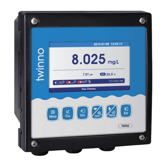
- Page 1 T6055 Online Residual Chlorine Meter Operating Manual 2019-01 -09 12:53:1 7 2019-01 -09 12:53:1 7 8. 02 5 mg/L mg/L 7.01 7.01 25.0 25.0 °C °C Free Chlorine Free Chlorine T6055 上海淳业仪表科技有限公司 Shanghai Chunye Instrument Technology Co.,Ltd...
-
Page 3: Table Of Contents
Table of Contents Preface Features Technical Specifications Installation Installation size Embedded installation Wall mounted installation Electrical connection Keypad descriptions Display descriptions Menu Calibration MODBUS RTU Daily Maintenance Package Set Warranty Notes... -
Page 4: Preface
Preface Thank you for your support. Please read this manual carefully before use.The correct use will maximize the performance and advantages of the product, and bring you a good experience. When receiving the instrument, please open the package carefully, check whether the instrument and accessories are damaged by transportation and whether the accessories are complete. -
Page 5: Technical Specifications
Technical Specification 0.005~20.00mg/L ; 0.005~20.00ppm Measurement range Measurement unit Membrane 0.001mg/L ; 0.001ppm Resolution ±1%F.S Basic error -2 16.00pH Measurement range Measurement unit 0.001pH Resolution ±0.01pH Basic error -10 150.0 ( Based on sensor) Temperature Temperature Resolution ±0.3 Temperature Basic error 2 groups: 4 20mA Current output RS485 Modbus RTU... -
Page 6: Installation
Instrument installation Installation size 118 mm 144 mm 26 mm Instrument dimensions M4x4 45x45 mm 138 mm +0.5 mm Back fixed hole size Embedded mounting Cut-out size... -
Page 7: Embedded Installation
Instrument installation: embedded installation a. Embedded in the opened hole b. Install a fixed frame for the instrument D+ D- Installation completion diagram Instrument installation:Wall mounted installation 150.3 mm 6x15 mm Installation completion diagram a. Install fixing bracket for instrument b.Wall screw fixing Install fixed bracket top view, pay attention to... -
Page 8: Electrical Connection
Instrument connection V+ V- A1 B1 V+ V- A2 B2 I1 G I2 A3 B3 G TX RX P+ P- REF2 INPUT2 TEMP2 TEMP2 T2+ T2- EC1 EC2 EC3 EC4 RLY3 RLY2 RLY1 V+,V-,A1,B1 REF1 pH/lon reference1 Digital input channel 1 V+,V-,A2,B2 INPUT1 pH/lon measurement1... -
Page 9: Keypad Descriptions
Keypad descriptions Keypad operation tips: Short press: Short press means to release the key immediately after pressing. (Short press if not specified below) Long press: Press and hold for 3 seconds and then release the key. Enter standard solution Menu setting mode: press this key to loop Confirmation down the menu options calibration mode... -
Page 10: Display Descriptions
Display descriptions All pipe connections and electrical connections should be checked before use. After the power is switched on, the meter will display as follows. Year-Month-Date Time Main measurment+ Unit 2019-01-09 12:53:17 8.025 Warning mg/L pH Compensation 7.01 25.0 °C +Unit Relay 1 [blue is off... -
Page 11: Menu
Menu structure The following is the menu structure of this instrument,press MENU key to enter menu setting mode: If the monitor prompts you to enter the calibration security password, press the【▼】 key or 【 】key to set the calibration security password, and then press the 【ENT】key to confirm the calibration security password.No initial password here,please enter directly by press【ENT】key. - Page 12 Output Current 1 Channel Main Temperature Output Option 4-20mA 0-20mA 20-4mA Upper Limit Lower Limit Current 2 Channel Main Temperature Output Option 4-20mA 0-20mA 20-4mA Upper Limit Lower Limit RS485 Baud Rate 4800BPS 9600BPS 19200BPS Parity Check None Even Stop Bit 1 Bit 2 Bit Network Node...
-
Page 13: Calibration
Calibration Press [MENU] to enter the setting mode and select the calibration Calibration Standard 0.01 (Default, can be modified) Calibration Point 1 Solution Calibration Point 2 2 (Default, can be modified) Calibration Calibration Point 3 5 (Default, can be modified) Calibration Point 4 10 (Default, can be modified) Calibration Point 5... - Page 14 Field Calibration Select on-site calibration methods: Linear calibration , Offset adjustment , linear adjustment . Field Calibration When the data from laboratory or portable instrument are input into this item, the instrument will automatically correct the data. Free Chlorine Field Calibration Field Calibration pH / ORP pH:7.00...
- Page 15 Graphic Trend(Trend Chart) Press Menu key to enter the setting mode,set the recording interval, and the instrument will Interval/point Curve 400 points per screen,displays the most recent Data Log query data trend graph according to interval Settings (trend chart) 1h/point 400 points per screen, display trend chart of the last 16 days of data 12h/point...
-
Page 16: Modbus Rtu
MODBUS RTU General Information Overview The hardware version number of this document is V2.0; the software version number is V5.9 and above. This document describes the MODBUS RTU interface in details and the target object is a software programmer. MODBUS command structure Data format description in this document;... - Page 17 MODBUS RTU Transmission Mode When the instrument uses RTU (Remote Terminal Unit) mode for MODBUS serial communication, each 8-bit byte of information contains two 4-bit hexadecimal characters. The main advantages of this mode are greater character density and better data throughput than the ASCII mode with the same baud rate.
- Page 18 Implementation of MODBUS RTU in Instrument According to the official MODBUS definition, the command starts with a 3.5 character interval triggering command, and the end of the command is also represented by a 3.5 character interval. The device address and MODBUS function code have 8 bits. The data string contains n*8 bits, and the data string contains the starting address of the register and the number of read/write registers.
- Page 19 MODBUS function code 0x10: write multiple registers This function code is used to write continuous registers to remote devices (1... 123 registers) block that specifies the value of the registers written in the request data frame. Data is packaged in two bytes per register.
- Page 20 Data format in instrument Overview Floating Point Definition: Floating point, conforming to IEEE 754 (single precision) Description Symbol Index Mantissa 30…23 22…0 22…0 Index Deviation Figure 14: floating point single-precision definition (4 bytes, 2 MODBUS registers) Example: Compile decimal 17.625 to binary Step 1: Converting 17.625 in decimal form to a floating-point number in binary form, first finding the binary representation of the integer part 17decimal= 16 + 1 = 1×2...
- Page 21 If it is large-end storage mode, after executing the above statement, the data stored in outdata of address unit is 0x41 Outdata + 1 stores data as 0x8D address unit (outdata + 2) stores data as 0x00 address unit (outdata + 3) stores data as 0x00 2.
- Page 22 Read instruction mode The communication protocol adopts MODBUS (RTU) protocol. The content and address of the communication can be changed according to the needs of customers. The default configuration is network address 01, baud rate 9600, even check, one stop bit, users can set their own changes;...
-
Page 23: Daily Maintenance
Daily maintenance According to the requirements of use, the installation position and working condition of the instrument are relatively complex. In order to make the instrument work normally, maintenance personnel need to carry out regular maintenance on the instrument. Please pay attention to the following matters during maintenance: 1. -
Page 24: Faq
1.LCD display is not bright Possible causes:Instrument or LCD Screen power supply failure. Solutions:Check whether the power supply is connected or not, and check whether the power supply wire of the sensor is connected in the wrong direction. 2.No current output Possible causes:It could be a fault in the current module or a wiring fault. -
Page 25: Warranty
Warranty We Instruments warrants this product to be free from significant deviations in material and workmanship for a period of one year from the date of purchase. If repair is necessary and has not been the result of abuse or misuse within the warranty period, please return to We Instruments and amendment will be made without any charge. -
Page 26: Notes
Notes Distinguished users, please pay attention to the following points when using the instrument, in order to ensure the life and accuracy of the instrument. Careful handling to avoid collision and falling instruments in use. Avoid contact with water or other liquids during use. Don't put the instrument in the sunshine for a long time. - Page 28 上海淳业仪表科技有限公司 Shanghai Chunye Instrument Technology Co.,Ltd Tel: 021-61621082 Fax: 021-61621099 Web: www.twinno.net Add: Building 6, No.166 Mindong Road, Pudong New District, Shanghai, China Post code:201209...
Need help?
Do you have a question about the T6055 and is the answer not in the manual?
Questions and answers