
Related Manuals for Twinno 16540


Summary of Contents for Twinno 16540
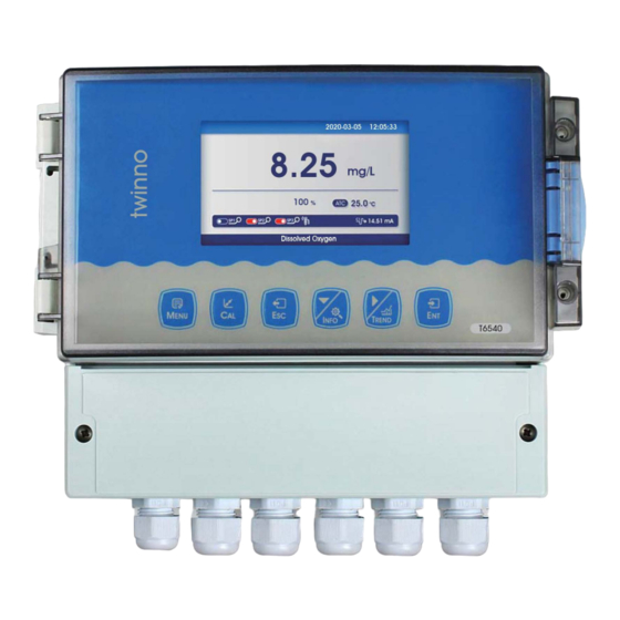
- Page 1 天 twin no 。 。 。 16540 graphic On-line Diss lved Oxygen Meter Operating Manual 上海淳业仪表科技杳限公司...
-
Page 2: Table Of Contents
Content Preface..............................1 Features............................... 2 Technical Specifications........................3 Instrument installation........................4 Keypad descriptions..........................6 Display description..........................7 Menu Structure........................... 8 Calibration............................11 Graphic Trend(Trend Chart).......................12 MODBUS RTU General Information....................13 MODBUS RTU Transmission Mode....................14 MODBUS RTU CRC Check........................16 Implementation of MODBUS RTU in Instrument................16 Instrument MODBUS RTU function code..................16 MODBUS function code 0x10: write multiple registers.............. -
Page 3: Preface
Preface Thank you for your support to us. Please read the instruction manual carefully before use to help you use our products correctly. When receiving the instrument, please carefully open the package, check whether the instrument and accessories are damaged by transportation, whether the accessories are complete, if abnormal, please contact our after-sales service department or regional customer service center, and keep the packaging for return processing. -
Page 4: Features
Features Industrial online dissolved oxygen meter is an online water quality monitor and control instrument with microprocessor. The instrument is equipped with different types of dissolved oxygen sensors. It is widely used in power plants, petrochemical industry, metallurgical electronics, mining, paper industry, food and beverage industry, environmental protection water treatment, aquaculture and other industries. -
Page 5: Technical Specifications
Technical Specifications Measurement range 0~40.00mg/L; 0~400.0% Measurement unit mg/L; % Resolution 0.01mg/L; 0.1% Basic error ±1%F.S Temperature -10~150℃ Temperature Resolution 0.1℃ Temperature Basic error ±0.3℃ Current Output 4~20mA,20~4mA,(load resistance<750Ω) Communication output RS485 MODBUS RTU Relay control contacts 5A 240VAC,5A 28VDC or 120VAC Power supply (optional) 85~265VAC,9~36VDC,power consumption≤3W Working conditions... -
Page 6: Instrument Installation
Instrument installation Installation size... - Page 7 Wiring Function Wiring Terminal Function Terminal SEN V+ Sensor Power+ NO 1 High set relay working position SEN V- Sensor Power- COM 1 Alarm relay common SEN A Sensor Communication A NC 1 High set relay resting position SEN B Sensor Communication B NO 2 Low set relay working position...
-
Page 8: Keypad Descriptions
Keypad descriptions Keypad operation tips: Short Press: Short Press means to release the key immediately after pressing. ((Default to short presses if not indicated below) Long Press: Long Press is to press the button for 3 seconds and then release it. -
Page 9: Display Description
Display description Before using should check all the pipe connection and electrical connection, after the power supply, the instrument is shown as:... -
Page 10: Menu Structure
Menu Structure The following is the menu structure of the instrument: Unit Mg/L Pressure compensation 101.3 Salinity compensation Sensor Anaerobic oxygen Configure voltage compensation Saturation oxygen voltage compensation Saturation oxygen compensation Temperature Sensor NTC2.252 kΩ NTC10 kΩ Pt100 Temperature Pt1000 Temperature Offset 0.0000 Temperature Input... - Page 11 High Alarm Relay 2 High/Low Alarm Low Alarm Cleaning(cleaning time is set in the cleaning output) Limit Value Hysteresis Status High Alarm High/Low Alarm Low Alarm Relay 3 Cleaning(cleaning time is set in the cleaning output) Limit Value Hysteresis Channel Main Temperature 4-20mA...
- Page 12 7.5s Record Interval 180s Memory information 101600point Data Output System Language Chinese English Year-Month-Day Date/Time Hour-Minute-Second Standard Display Speed Medium Display High Backlight Saving Bright Soft Version 19-1.0 Soft Version Password Settings 0000 Serial Number 1.No Factory Default 2.Yes Current 1 4mA (The positive and negative ends of the ammeter are Current 1 20mA...
-
Page 13: Calibration
Calibration Press [MENU] to enter the setting mode and select the calibration: Anaerobic calibration Standard Solution Calibration Air calibration Field Calibration Calibration Offset Adjustment Field Calibration Slope Adjustment Calibration of Standard Solution Select the way of Calibration, press the【ENT】 key to enter the Standard Solution Calibration. -
Page 14: Graphic Trend(Trend Chart)
Field calibration Select field calibration mode: [field calibration], [Offset adjustment], [linear adjustment]. When the data from laboratory or portable instrument are input into this item, the 【▼】【▶ /TREND】, instrument will automatically correct the data. Input data by press 【ENT】to calibrate, Done means succeed, Press【ESC】to exit. -
Page 15: Modbus Rtu General Information
Press the button returns to the measurement screen. Press the 【Menu】 /TREND】button in the measurement mode to view the trend chart of the saved 【▶ data directly. There are 400 sets of data record per screen. In the current mode, press the key to move the data display line to the left and 【ENT】... -
Page 16: Modbus Rtu Transmission Mode
Command Structure The MODBUS application protocol defines the Simple Protocol Data Unit (PDU), which is independent of the underlying communication layer. Figure 1: MODBUS Protocol Data Unit MODBUS protocol mapping on a specific bus or network introduces additional fields of protocol data units. The client that initiates the MODBUS exchange creates the MODBUS PDU, and then adds the domain to establish the correct communication PDU. - Page 17 Each 8-bit byte in a message contains two 4-bit hexadecimal characters (0-9, A-F) Bits in each byte: 1 starting bit 8 data bits, the first minimum valid bits without parity check bits 2 stop bits Baud rate: 9600 BPS How characters are transmitted serially: Each character or byte is sent in this order (from left to right) the least significant bit (LSB)...
-
Page 18: Modbus Rtu Crc Check
MODBUS RTU CRC Check The RTU mode contains an error-detection domain based on a cyclic redundancy check (CRC) algorithm that performs on all message contents. The CRC domain checks the contents of the entire message and performs this check regardless of whether the message has a random parity check. - Page 19 two bytes per register. For each register, the first byte contains high bits and the second byte contains low bits. Request Function code 1 byte 0x03 Start Address 2 bytes 0x0000….0xfffff Read register number 2bytes 1...125 Figure 8: Read-and-hold register request frame Response Function code 1 byte...
-
Page 20: Modbus Function Code 0X10: Write Multiple Registers
Function code 0x64 Figure 10: Examples of read and hold register request and response frames MODBUS function code 0x10: write multiple registers This function code is used to write continuous registers to remote devices (1... 123 registers) block that specifies the value of the registers written in the request data frame. -
Page 21: Data Format In Instrument
Input register number 0x04 Input register number (low bytes) (low bytes) number of bytes 0x00 Register value (high 0x0A byte) Register value (low 0x01 byte) Register value (high 0x02 byte) Register value (low byte) Figure 13: Examples of writing multiple register request and response frames Data format in instrument Overview Floating Point... - Page 22 10001.101B = 1.0001101 B× 24 . So the exponential part is 4, plus 127, it becomes 131, and its binary representation is 10000011B. Step 3: Calculate the tail number After removing 1 before the decimal point of 1.0001101B, the final number is 0001101B (because before the decimal point must be 1, so IEEE stipulates that only the decimal point behind can be recorded).
- Page 23 2. If the compiler used by the user does not implement the library function of this function, the following functions can be used to achieve this function: void memcpy(void *dest,void *src,int n) char *pd = (char *)dest; char *ps = (char *)src; for(int i=0;i<n;i++) *pd++ = *ps++;...
-
Page 24: Read Instruction Mode
M = ((realbyte1&0x7f) << 16) | (realbyte2<< 8)| realbyte3; D = pow(-1,S)*(1.0 + M/pow(2,23))* pow(2,E); return D; Function description: parameters byte0, byte1, byte2, byte3 represent 4 bytes of binary floating point number( the return value Converted the decimal number For example, the user sends the command to get the temperature value and dissolved oxygen value to the probe. -
Page 25: Saturated Oxygen Meter In Water At Different Temperatures
Slave Response: 01 04 10 00 00 41 A0 00 00 41 20 00 00 42 C8 00 00 43 48 81 E8 Note: [01] Represents the instrument communication address; [04] Represents function code 04; [10] represents 10H (16) byte data; [00 00 00 41 A0] = 20.0;... -
Page 26: Daily Maintenance
follows. Daily maintenance Generally, the instrument does not need daily maintenance. If there is any fault, you can contact our company and carry out adjustment and repair under the guidance of our technical personnel.If the user has no check condition or needs maintenance, please contact the manufacturer. -
Page 27: Frequently Asked Questions
Frequently Asked Questions 1.LCD display is not bright Possible causes:Instrument or LCD Screen power supply failure. Solutions:Check whether the power supply is connected or not, and check whether the power supply wire of the sensor is connected in the wrong direction. 2.No current output Possible causes:It could be a fault in the current module or a wiring fault. -
Page 28: Package Set
Package Set Product Description Quantity 1) T6540 Online Dissolved Oxygen Meter 2) Instrument Installation Accessories 3) Operating Manual 4) Qualification Certificate... -
Page 29: Warranty
Warranty We guarantee that there will be no significant deviation between material and process within one year from the date of purchase. During the warranty period, if necessary repair is not caused by improper use or misoperation, please pay the transportation fee to return the instrument, and we will repair it free of charge. -
Page 30: Notes
Notes Distinguished users, please pay attention to the following points when using the instrument, in order to ensure the life and accuracy of the instrument. Careful handling to avoid collision and falling instruments in use. Avoid contact with water or other liquids during use. ...
Need help?
Do you have a question about the 16540 and is the answer not in the manual?
Questions and answers