Table of Contents
Advertisement
Quick Links
Advertisement
Table of Contents
Troubleshooting

Related Manuals for Arjo Enterprise E8000X


Summary of Contents for Arjo Enterprise E8000X
- Page 1 SERVICE MANUAL Enterprise E8000X (E8X) For internal use only 746-587_5 • 09/2021...
- Page 2 This manual is intended for use by Arjo approved service technicians. The manual may be provided to a customer in response to customer requirements, but in no event will Arjo be responsible for any service or repair performed by customers.
-
Page 3: Table Of Contents
TABLE OF CONTENTS CHAPTER 1 Introduction ............1 About This Manual. - Page 4 Foot End Split Side Rail - Replacement ....... . 66 Split Side Rail Damper - Replacement.
-
Page 5: Introduction
CHAPTER 1 INTRODUCTION About This Manual This manual contains information on servicing and maintenance of the Arjo Enterprise ® E8000X bed. The manual comprises the following Chapters: Chapter 1 Introduction (this chapter): General description of the equipment with an explanation of the various features available, together with contact details for Arjo around the world. -
Page 6: Product Description
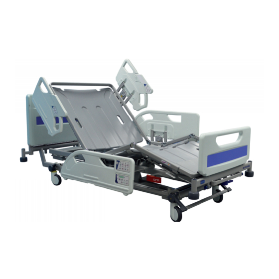
Introduction Enterprise E8000X Service Manual Product Description The Enterprise E8000X is an electrically operated acute care medical bed. The bed has multiple functions to provide the best nursing position for both patient and carer. Scope This service manual covers all Enterprise E8000X models. - Page 7 Enterprise E8000X Service Manual Introduction Figure 1: Enterprise E8000X All power-operated functions are operated by push button controls. Each function has separate “up” and “down” pushbuttons. The user control panels are integrated into the head end split side rail modules, with the patient's controls on the inside face and the nurse's controls on the outside.
- Page 8 Introduction Enterprise E8000X Service Manual This Page Intentionally Left Blank Page 4...
-
Page 9: Decontamination
Enterprise E8000X Service Manual Decontamination CHAPTER 2 DECONTAMINATION WARNING Disconnect the bed from the mains power supply before carrying out cleaning procedures. Do not allow the mains plug or power supply cord to get wet when cleaning the bed. Cleaning Wearing suitable protective clothing, clean all surfaces with a disposable cloth soaked in a neutral detergent and hand hot water. - Page 10 Decontamination Enterprise E8000X Service Manual This Page Intentionally Left Blank Page 6...
-
Page 11: Preventive Maintenance
Enterprise E8000X Service Manual Preventive Maintenance CHAPTER 3 PREVENTIVE MAINTENANCE This product has been designed to be virtually maintenance-free between service intervals. The degree of periodic maintenance required will be determined by use and condition. The following preventive maintenance checks and procedures should be carried out every 12 months. -
Page 12: Battery Test
If this test is not completed successfully, connect the bed to the electricity supply for at least eight hours to recharge the battery then perform the test again. If the bed fails a second time, contact Arjo or an approved service agent. -
Page 13: Testing
Enterprise E8000X Service Manual Testing CHAPTER 4 TESTING The following serviceability tests should be performed before returning the bed to use after service, or if any function is suspect. These instructions should be read in conjunction with the instructions for use supplied with the product (part number 746-585). -
Page 14: Manual Functions
Testing Enterprise E8000X Service Manual Battery Operation Check operation of the battery by completing the steps described in section Battery Test (refer to Chapter 3, Section 3). Manual Functions The following tests check functions that are not electrically powered: Brakes and Steering Check the brakes for efficient operation. -
Page 15: Troubleshooting
Enterprise E8000X Service Manual Troubleshooting CHAPTER 5 TROUBLESHOOTING Fault finding The following table identifies some fault symptoms, possible cause(s) and suggested remedial action. Symptom Possible cause Remedial action All actuators inoperative Functions locked on ACP Unlock functions on ACP Power disconnected and... - Page 16 Troubleshooting Enterprise E8000X Service Manual Backrest actuator Thigh actuator All LEDs Flashing at 1Hz Control unit A loss of position in either the high or low actuator. To reset: 1. Hold down both the high and low buttons on the ACP for 10 seconds.
-
Page 17: Fatal Error Troubleshooting
Enterprise E8000X Service Manual Troubleshooting Fatal Error Troubleshooting Installation The hardware is available under index S9411 and contains (SDT box and RJ45 10-wires cable). Standard cable USB A-B is not supported. NOTE Do not connect SDT together with Linak programming tool Download installation file. - Page 18 Troubleshooting Enterprise E8000X Service Manual Fatal Error H-Bridge Diagram Page 14...
- Page 19 Enterprise E8000X Service Manual Troubleshooting Fatal Error Actuator Diagram Page 15...
-
Page 20: Linak Service Data Tool
Troubleshooting Enterprise E8000X Service Manual Linak Service Data Tool Linak Service Data Tool (SDT) Connection Connect USB cable from PC to Data Readout Box. Connect OpenBus cable from Data Readout Box to bed (any available OpenBus port, i.e. in MJB). -
Page 21: Servicing Instructions
Use only replacement parts that are approved by Arjo. Use only parts listed in this chapter; similar parts from other Arjo products may not be compatible. If single use fasteners are removed they should always be replaced with new parts. - Page 22 Servicing Instructions Enterprise E8000X Service Manual • Perform a serviceability test as described in “Testing” on page 9. • Clean the equipment as described in “Decontamination” on page 5. Page 18...
- Page 23 Enterprise E8000X Service Manual Servicing Instructions Product Identification The model number and serial number can be found on the specification label; this is located on the bed frame below the head board. Specification label At the time of ordering the optional features on the bed were specified. These optional features can be identified by reading the model number REF on the specification label.
- Page 24 Servicing Instructions Enterprise E8000X Service Manual Actuator Cable Clips Where cables are connected to actuators they are held in place by retaining clips. Figure 2: Actuator cable clip To release the clip, use a small screwdriver to press in the retaining lugs on either side of the socket (Fig 2, Item A) and pull the clip out (B).
-
Page 25: Tools And Equipment
Enterprise E8000X Service Manual Servicing Instructions Tools and Equipment In addition to normal workshop tools, the special tools and equipment listed below may be required for servicing. Item Description Part No. Used for Hoist, SWL 250kg General lifting Sling straps (2), SWL 250kg... -
Page 26: Electrical Assembly
Servicing Instructions Enterprise E8000X Service Manual Electrical Assembly Page 22... - Page 27 Enterprise E8000X Service Manual Servicing Instructions Page 23...
- Page 28 Servicing Instructions Enterprise E8000X Service Manual Page 24...
- Page 29 Enterprise E8000X Service Manual Servicing Instructions Page 25...
- Page 30 Servicing Instructions Enterprise E8000X Service Manual Page 26...
- Page 31 Enterprise E8000X Service Manual Servicing Instructions Page 27...
- Page 32 Servicing Instructions Enterprise E8000X Service Manual Page 28...
- Page 33 Enterprise E8000X Service Manual Servicing Instructions Figure 3: Sub-Frame & Sections Assembly Page 29...
-
Page 34: Sub Frame & Sections Assembly
Servicing Instructions Enterprise E8000X Service Manual Sub Frame & Sections Assembly Throughout this chapter reference is made to the Sub-Frame & Sections Assembly. It is recommended to bookmark this page for later use. Table 1: Sub-Frame & Sections Assembly Parts List... - Page 35 Enterprise E8000X Service Manual Servicing Instructions Figure 4: Sub Frame Assembly Page 31...
-
Page 36: Sub Frame Assembly
Servicing Instructions Enterprise E8000X Service Manual Sub Frame Assembly Throughout this chapter reference is made to the Sub Frame Assembly. It is recommended to bookmark this page for later use. Table 2: Sub Frame Assembly Parts List Item Part Number Description 828.313... - Page 37 Enterprise E8000X Service Manual Servicing Instructions Table 2: Sub Frame Assembly Parts List Item Part Number Description 828.313 828.918 828.402 Mains cable anchor rear 828.403 Mains cable anchor front S3408 Screw M5 x 35 Mains cable (see drawing 828.476 for E8X, drawing 828.306 for E5X)
-
Page 38: Brake Pedal - Replacement
Servicing Instructions Enterprise E8000X Service Manual Brake Pedal - Replacement This section describes how to replace brake pedals. Reference is made throughout this section to Figure 5 on page 36 and Table 3 on page 37. Removal To remove the brake pedals: 7.1.1 Position the bed so that all the castors are lined up in the same direction and apply the brakes. -
Page 39: Castors - Replacement
Enterprise E8000X Service Manual Servicing Instructions Castors - Replacement This section describes how to replace the castors. Reference is made throughout this section to Figure 5 on page 36 and Table 3 on page 37. Take care to ensure replacement castors are the same type (brake/free or brake/track) and wheel size as the old one. - Page 40 Servicing Instructions Enterprise E8000X Service Manual Torque item 12 to 10.2 Nm. Figure 5: Brake and Castor Module The type of castors and brakes installed on the bed can be identified from the model number REF on the specification label, refer to Chapter 6, Subsection 1.1.
- Page 41 Enterprise E8000X Service Manual Servicing Instructions Table 3: Brake and Castor Module Parts List Item Part Number Description A B C D L M N P Brake bow 828.047 tube Brake pedal 828.147 blanking cap Brake pedal Left hand / 828.237 Kit...
- Page 42 Servicing Instructions Enterprise E8000X Service Manual Table 3: Brake and Castor Module Parts List Item Part Number Description A B C D L M N P 125mm brake/track 828.241 Kit castor Head 125mm brake/free 828.240 Kit castor Head 150mm brake/track 828.243 Kit...
- Page 43 Enterprise E8000X Service Manual Servicing Instructions Figure 6: Control box and battery Table 4: Control box and battery parts list Item Part Number Description S1410 Nyloc nut M5 THK S4785 External tooth washer S3456 POZI PAN head screw M5 x 16 BA18 battery box 828.771 Kit...
-
Page 44: Backup Battery - Replacement
Servicing Instructions Enterprise E8000X Service Manual Backup Battery - Replacement This section describes how to replace the backup battery. Reference is made throughout this section to Figure 6 on page 39 and “Electrical Assembly” on page 22. Check the following characters on the product label (refer to Chapter 6, Subsection 1.1). - Page 45 Enterprise E8000X Service Manual Servicing Instructions 9.1.3 Remove two panhead Pozidriv screws (Fig 6, Item 3) to detach the backup battery (Fig 6, Item 4) from the mounting plate (E). Collect four Nyloc nuts (Fig 6, Item 1) and remove the battery from the bed.
-
Page 46: Mains Lead - Replacement
Servicing Instructions Enterprise E8000X Service Manual Mains Lead - Replacement This section describes how to replace mains lead. Reference is made throughout this section to (“Electrical Assembly” on page 22). Check the following characters on the product label (refer to Chapter 6, Subsection 1.1). - Page 47 Enterprise E8000X Service Manual Servicing Instructions 10.2 Installation To install the mains lead: 10.2.1 Plug the mains lead (“Electrical Assembly” on page 22, Item 9) into the control box (Fig 6, Item 5). Make sure that the retaining clip “clicks” into place and that the mains lead cannot be accidentally pulled out of the control box.
-
Page 48: Control Box - Replacement
Servicing Instructions Enterprise E8000X Service Manual Control Box - Replacement This section describes how to replace the electrical control box. Reference is made throughout this section to Figure on (“Electrical Assembly” on page 22) and (Fig 6, Item 5). 11.1... - Page 49 Enterprise E8000X Service Manual Servicing Instructions 11.2.3 Connect the four actuator cables (“Electrical Assembly” on page 22, Item 15/16/17/18) and OpenBus cable (“Electrical Assembly” on page 22, Item 19 and 20) to the control box, making sure each cable is connected to the correct socket as previously noted. Thread the retainer (Fig 10, Item A) over the cables and clip it into place.
-
Page 50: Deck Junction Box - Replacement
Servicing Instructions Enterprise E8000X Service Manual Deck Junction Box - Replacement This section describes how to replace the deck junction box. Reference is made throughout this section to Figure 3 on page 29. There are two deck junction boxes on either side of the bed frame. The deck junction boxes also contain the under bed lights. - Page 51 Enterprise E8000X Service Manual Servicing Instructions Figure 13: Safety Side Assembly Foot End Table 6: Safety Side Assembly Foot End Parts List Item Part Description 828.376 828.377 832.963 832.964 Number S-Side Assy S-Side Assy S-Side Assy S-Side Assy FE-RH FE-LH...
-
Page 52: Attendant Control Panel - Replacement
Servicing Instructions Enterprise E8000X Service Manual Attendant Control Panel - Replacement This section describes how to replace the Attendant Control Panel (ACP). Reference is made throughout this section to (“Electrical Assembly” on page 22) and (Figure 13 on page 47). - Page 53 Enterprise E8000X Service Manual Servicing Instructions Figure 15: Safety Side Assembly Head End Table 7: Safety Side Assembly Head End Parts List Item Part Number Description 828.374 S-Side 828.375 S-Side 832.961 S-Side 832.962 S-Side Assy HE-RH Assy HE-LH Assy HE-RH...
-
Page 54: Patient Control Unit - Replacement
Servicing Instructions Enterprise E8000X Service Manual Patient Control Unit - Replacement This section describes how to replace the Patient Control Unit. Reference is made throughout this section to “Electrical Assembly” on page 22 and Figure 15 on page 49. 14.1... -
Page 55: Height Actuator - Replacement
Enterprise E8000X Service Manual Servicing Instructions Height Actuator - Replacement This section describes how to replace the height actuator. Reference is made throughout this section (“Electrical Assembly” on page 22) and (Figure 4 on page 31). WARNING Before removing the height actuator ensure that the sub-frame is securely supported on suitable stands or blocks. - Page 56 Servicing Instructions Enterprise E8000X Service Manual Actuator Starlock Clevis pin Shakeproof washer Figure 16: Actuator fasteners 15.2.3 Fit the clevis pin (Fig 4, Item 8) and shakeproof washer (Fig 4, Item 21) to attach the actuator ram to the radius arm. Secure with a new starlock (Fig 4, Item 9). Make sure the shakeproof washer and starlock fit tightly against the mounting bracket as shown in Figure 16.
-
Page 57: Backrest Actuator - Replacement
Enterprise E8000X Service Manual Servicing Instructions Backrest Actuator - Replacement This section describes how to replace the backrest actuator. Reference is made throughout this section to “Electrical Assembly” on page 22, Figure 3 on page 29 and Figure 4 on page 31. -
Page 58: Thigh Actuator - Replacement
Servicing Instructions Enterprise E8000X Service Manual Thigh Actuator - Replacement This section describes how to replace the thigh actuator. Reference is made throughout this section to “Electrical Assembly” on page 22 and Figure 3 on page 29. WARNING Ensure that the foot end of the mattress platform is securely supported before removing the thigh actuator. - Page 59 Enterprise E8000X Service Manual Servicing Instructions Backrest actuator cables Figure 17: CPR cable fixing - backrest actuator Figure 18: CPR Cable routing Page 55...
-
Page 60: Cpr Release Handle And Cable - Replacement
Servicing Instructions Enterprise E8000X Service Manual CPR Release Handle and Cable - Replacement This section describes how to replace the CPR release handle and cable. Reference is made throughout this section to “Electrical Assembly” on page 22 and Figure 4 on page 31. -
Page 61: Backrest Damper - Replacement
Enterprise E8000X Service Manual Servicing Instructions Backrest Damper - Replacement This section describes how to replace the backrest damper. Reference is made throughout this section to Figure 3 on page 29. 19.1 Removal To remove the backrest damper: 19.1.1 Raise the backrest to maximum height. If the backrest actuator (Fig 3, Item 7) has been removed, use the hoist to support the backrest in position. - Page 62 Servicing Instructions Enterprise E8000X Service Manual This Page Intentionally Left Blank Page 58...
- Page 63 Enterprise E8000X Service Manual Servicing Instructions Figure 19: Bed Extension / Bed Stripper Assembly Table 8: Bed Extension / Bed Stripper Assembly Parts List Item Part Number Description Bed extension fabrication 828.210 Kit 828.008 Bed extension guide 818.126 Panel socket liner Bed extension locking fabrication 828.209 Kit...
-
Page 64: Bed Extension / Bed Stripper - Replacement
Servicing Instructions Enterprise E8000X Service Manual Bed Extension / Bed Stripper - Replacement This section describes how to replace the bed extension and optional bed stripper. Reference is made throughout this section to Figure 19 on page 59. Check the following character on the product label (refer to Chapter 6, Subsection 1.1). - Page 65 Enterprise E8000X Service Manual Servicing Instructions Figure 20: Safety Side Arm Assembly Table 9: Safety Side Arm Assembly Parts List Item Part Number Description 818.607 S-S Plunger Mk5 RH 818.606 S-S Plunger Mk5 LH 818.611 S-Side lower arm Mk5 818.146 S-Side lower arm pivot, bottom 828.639...
-
Page 66: Head End Split Side Rail - Replacement
The characters at the highlighted positions on the product label indicate the backrest and side rail configuration (refer to Chapter 6, Subsection 1.1). The Enterprise E8000X will always have a number 3 and letter B at these positions meaning that the bed is fitted with Standard Backrest and Split Side Rails. - Page 67 Enterprise E8000X Service Manual Servicing Instructions Figure 21: Safety Side Module Table 10: Safety Side Module Parts List Qty EX8 Qty EX8 (SD) Item Part Number Description (figure (Figure S-Side Foot Assy - RH 828.376 832.963 S-Side Foot Assy - LH 828.377...
- Page 68 Servicing Instructions Enterprise E8000X Service Manual Table 10: Safety Side Module Parts List Qty EX8 Qty EX8 (SD) Item Part Number Description (figure (Figure 832.987 Distance sleeve 832.988 Distance sleeve 5K1836G M4 X 16 HEX head posidrve screw 6100635 Screw M6S M6 X 35 A4 DIN 931...
- Page 69 Enterprise E8000X Service Manual Servicing Instructions Page 65...
-
Page 70: Foot End Split Side Rail - Replacement
Servicing Instructions Enterprise E8000X Service Manual Foot End Split Side Rail - Replacement This section describes how to replace the foot end split side rail. Reference is made throughout this “Electrical Assembly” on page 22, Figure 20 on page 61 and Figure 21 on page 63. -
Page 71: Split Side Rail Damper - Replacement
Enterprise E8000X Service Manual Servicing Instructions Split Side Rail Damper - Replacement This section describes how to replace the split side rail damper. Reference is made throughout this section to Figure 21 on page 63. 23.1 Removal To remove the split side rail damper: 23.1.1 Unscrew the split side rail damper assembly (Fig 21, Item 8) from the housing (Fig 21, Item 9);... - Page 72 Servicing Instructions Enterprise E8000X Service Manual Figure 23: Roller buffer Table 11: Roller Buffer Parts List Item Part Number Description Bed extension fabrication 828.210 Kit Corner tube liner 828.277 Kit Roller buffer moulding 828.205 Kit S4785 External shakeproof washer S7002...
-
Page 73: Side Rail Soft Drop Damper And Bracket - Replacement (Optional)
Enterprise E8000X Service Manual Servicing Instructions Side Rail Soft Drop Damper and Bracket - Replacement (optional) This section describes how to replace the split side rail Damper and Bracket. Reference is made throughout this drawings. “Side rail modules (soft drop)” (Figure 22), “Soft drop damper - replacement”... - Page 74 Servicing Instructions Enterprise E8000X Service Manual 24.2 Installation Brackets: 24.2.1 Take the appropriate bracket (Fig 22, Item 13-16) to the replacement point on the bed. 24.2.2 The mounting of the bracket varies depending on where it is placed on the bed: If you attach the bracket to the middle of the bed, its position after tightening a should be as horizontal as possible.
- Page 75 Enterprise E8000X Service Manual Servicing Instructions Figure 25: Soft drop backrest bracket - replacement Table 12: Side rail assembly replacement kits Panel Kit P/N Detailed description RH Foot 832.724 Enterprise 8000X, safety side RH foot, kit RH Foot (Soft Enterprise 8000X, safety side RH foot, kit (SD) 833.033...
-
Page 76: Roller Buffer - Replacement
Servicing Instructions Enterprise E8000X Service Manual Roller Buffer - Replacement This section describes how to replace the roller buffer. Reference is made throughout this section to Figure 23 on page 68. This procedure describes the replacement of the foot end roller buffer and/or corner tube liner;... - Page 77 Enterprise E8000X Service Manual Servicing Instructions Figure 26: Panel infill Table 13: Head/Footboard infill module Item Part Number Description 828.421 Kit Head end panel corporate lilac 828.422 Kit Head end panel light blue 828.423 Kit Head end panel corp’ blue 828.231 Kit...
- Page 78 Servicing Instructions Enterprise E8000X Service Manual Page 74...
- Page 79 Enterprise E8000X Service Manual Servicing Instructions Page 75...
- Page 80 Servicing Instructions Enterprise E8000X Service Manual HEADBOARD • FOOTBOARD INFILL MODULE 828.415 - Continues on next page Page 76...
- Page 81 Enterprise E8000X Service Manual Servicing Instructions Page 77...
- Page 82 Servicing Instructions Enterprise E8000X Service Manual Page 78...
- Page 83 Enterprise E8000X Service Manual Servicing Instructions HEADBOARD • FOOTBOARD INFILL MODULE 828.415 - Continuing from previous page Page 79...
-
Page 84: Restoration Of Paintwork
Servicing Instructions Enterprise E8000X Service Manual Restoration of Paintwork Damage to the paint finish on the frame or other components can be repaired by brush application of cellulose-based paint obtainable from specialist paint suppliers or local distributors. The standard finish colour for this product is silver (Beckers Ikea No. 1). - Page 85 Enterprise E8000X Service Manual Servicing Instructions For item 6 add Loctite ® Figure 27: Calf Extension Assembly Table 14: Calf Extension Assembly Parts List Item Part Number Description Calf section fabrication 828.222 Kit Calf extension piece fab 828.221 Kit 818.85 Hinge - inner 818.97...
- Page 86 Servicing Instructions Enterprise E8000X Service Manual Calf section and calf section stay – replacement This section describes how to replace the calf section and calf section stay. Reference is made throughout this section to Figure 27 on page 81 and Figure 29 on page 84.
- Page 87 Enterprise E8000X Service Manual Servicing Instructions Figure 28: Location of calf section stay Page 83...
- Page 88 Servicing Instructions Enterprise E8000X Service Manual Figure 29: Thigh Section Assembly Table 15: Thigh Section Assembly Parts List Item Part Number Description Thigh section fabrication 818.86 Hinge outer 818.85 Hinge inner S4529 Pop rivet Ø6.4 x 15 long S6526 Nylon rivet plug 818.105...
-
Page 89: Thigh Section - Replacement
Enterprise E8000X Service Manual Servicing Instructions Thigh section – replacement This section describes how to replace the thigh section. Reference is made throughout this section to Figure 3 on page 29, Figure 4 on page 31 and Figure 29 on page 84. -
Page 90: Stabiliser Arm - Replacement
Servicing Instructions Enterprise E8000X Service Manual Stabiliser arm – replacement This section describes how to replace the stabiliser arm. Reference is made throughout this section to Figure 3 on page 29 and Figure 4 on page 31. 29.1 Removal To remove the stabiliser arm: 29.1.1 Adjust the mattress platform to a mid-height position, about 50-60cm above the floor. -
Page 91: Radius Arm Slide Mouldings - Replacement
Enterprise E8000X Service Manual Servicing Instructions Radius arm slide mouldings – replacement This section describes how to replace the radius arm slide mouldings. Reference is made throughout this section to Figure 4 on page 31. WARNING Ensure that the sub-frame is securely supported, either with the hoist or suitable blocks/stands, at all times. -
Page 92: Calf Section And Calf Section Stay - Replacement
Servicing Instructions Enterprise E8000X Service Manual Calf extension sheet – replacement This section describes how to replace the calf extension sheet. The calf extension sheet is attached to the mattress platform calf section by an integral moulded lip. Lift up the calf extension sheet to remove it. -
Page 93: Calf Ratchet Moulding - Replacement
Enterprise E8000X Service Manual Servicing Instructions Calf ratchet moulding – replacement This section describes how to replace the calf ratchet moulding. Reference is made throughout this section to Figure 4 on page 31. 32.1 Removal To remove the calf ratchet moulding: 32.1.1 Remove the calf extension sheet and calf section deck moulding. -
Page 94: Sleeve Bearing - Replacement
Servicing Instructions Enterprise E8000X Service Manual Sleeve Bearing – Replacement This section describes how to replace the sleeve bearing. Reference is made throughout this section to (“Height Actuator - Replacement” on page 51), to disassemble the radius arm from the height actuator. -
Page 95: Chapter 7 Technical Data
Enterprise E8000X Service Manual Technical Data CHAPTER 7 TECHNICAL DATA General Safe working load 250kg Maximum patient weight 185kg Product weight (approx.) 150kg Audible noise 50dB approx. Operating conditions Temperature 5°C to 40°C Relative humidity 20% to 90% at 30°C, non-condensing... - Page 96 Incorrect disposal of this equipment and its component parts, particularly gas springs, actuators, batteries and other electrical devices, may produce substances that are hazardous to the environment. To minimise these hazards, contact Arjo for information on correct disposal. Transport and storage Handle with care.
- Page 97 Enterprise E8000X Service Manual Technical Data Caution If the bed is stored for a long time, it should be connected to the electricity supply for 24 hours every three months to recharge the backup battery, otherwise it may become unserviceable.
- Page 98 Technical Data Enterprise E8000X Service Manual Recommended mattress size Recommended patient height Calf section vascular position Mattress platform extension Page 94...
-
Page 99: Safe Disposal Of Gas Springs
Enterprise E8000X Service Manual Technical Data SAFE DISPOSAL OF GAS SPRINGS Gas springs contain air and oil at high pressure and must be vented in accordance with the following instructions before being discarded. Under no circumstances should any attempt be made to open the device. -
Page 100: Electromagnetic Compatibility
Technical Data Enterprise E8000X Service Manual ELECTROMAGNETIC COMPATIBILITY Caution The use of non-approved accessories may result in increased emissions or reduced immunity of the equipment. A list of approved accessories is included in the product instructions for use. When this equipment is used adjacent to other electronic devices, the user should observe the equipment to verify normal operation. - Page 101 Enterprise E8000X Service Manual Technical Data Guidance and manufacturer’s declaration – electromagnetic immunity The bed is intended for use in the electromagnetic environment specified below. The customer or the user of the bed should assure that it is used in such an environment.
- Page 102 Technical Data Enterprise E8000X Service Manual Guidance and manufacturer’s declaration – electromagnetic immunity The bed is intended for use in the electromagnetic environment specified below. The customer or the user of the bed should assure that it is used in such an environment.
- Page 103 Enterprise E8000X Service Manual Technical Data Recommended separation distances between portable and mobile RF communications equipment and the bed The bed is intended for use in an electromagnetic environment in which radiated RF disturbances are controlled. The customer or the user of the bed can help prevent electromagnetic interference by...
- Page 104 This Page Intentionally Left Blank...
- Page 105 At Arjo, we are committed to improving the everyday lives of people affected by reduced mobility and age-related health challenges. With products and solutions that ensure ergonomic patient handling, personal hygiene, disinfection, diagnostics, and the effective prevention of pressure ulcers and venous thromboembolism, we help professionals across care environments to continually raise the standard of safe and dignifi...
Need help?
Do you have a question about the Enterprise E8000X and is the answer not in the manual?
Questions and answers