Table of Contents
Advertisement
Advertisement
Table of Contents

Related Manuals for DynAmp LKAT2


Summary of Contents for DynAmp LKAT2
- Page 1 LKAT2 4PC EMC BI-DIRECTIONAL HIGH CURRENT MEASUREMENT SYSTEM with RECTIFIER PROTECTION FUNCTION Installation, Operation and Service Manual Manual Item No. 047314 Rev. A DynAmp, LLC 3735 Gantz Road Phone +1 614.871.6900 www.dynamp.com Grove City, Ohio 43123 USA Fax +1 614.871.6910...
- Page 2 LKAT Portable Installation, Operation and Service Manual This Page is Intentionally Blank © 2018 DynAmp, LLC Page ii 047312 A...
-
Page 3: Dynamp, Llc Warranty
Items and components not manufactured and resold by DynAmp, LLC are warranted by their manufacturer. Warranty repair shall be, at DynAmp’s option, in the form of repair or replacement of the defective items or components. Concerning warranty repairs, DynAmp, LLC will be responsible for DynAmp provided time, material and transportation costs (shipping or travel). - Page 4 LKAT Portable Installation, Operation and Service Manual This Page is Intentionally Blank © 2018 DynAmp, LLC Page iv 047312 A...
-
Page 5: Table Of Contents
DYNAMP, LLC WARRANTY ________________________________________________ iii TABLE OF CONTENTS ____________________________________________________ v HAZARD WARNING! _____________________________________________________ vii SAFETY ________________________________________________________________ ix DYNAMP, LLC CUSTOMER SUPPORT & SERVICE ASSISTANCE _________________ xi MANUAL REVISIONS ____________________________________________________ xiii HANDLING AND STORAGE ____________________________________________________ 1 PRODUCT DESCRIPTION _____________________________________________________ 3 2.1 SYSTEM OVERVIEW ......................3 2.2 ADDITIONAL MEASURING HEAD DETAIL ................ - Page 6 System Specifications (subject to change without notice) ......9 Table 5.1 Troubleshooting an Accuracy Diagnostics Fault Indication ........24 Table 5.2 Trip Configuration Details ..................27 Table 6.1 Spare Parts List ......................30 Table 7.1 Drawing List ......................31 © 2018 DynAmp, LLC Page vi 047312 A...
-
Page 7: Hazard Warning
GENERAL the unit. DynAmp, LLC does not assume liability for the customer’s failure to comply with the rules and requirements provided in this manual. This equipment is designed to be connected to hazardous electric voltages. - Page 8 LKAT Portable Installation, Operation and Service Manual This Page is Intentionally Blank © 2018 DynAmp, LLC Page viii 047312 A...
-
Page 9: Safety
If a binding screw is used for the mains earth connection, the binding screw must be size M4 (No. 6) or larger. DynAmp, LLC does not assume liability for the customer’s failure to comply with the rules and requirements provided in this manual. - Page 10 LKAT Portable Installation, Operation and Service Manual This Page is Intentionally Blank © 2018 DynAmp, LLC Page x 047312 A...
-
Page 11: Dynamp, Llc Customer Support & Service Assistance
LKAT Portable Installation, Operation and Service Manual DynAmp, LLC Customer Support & Service Assistance For further assistance, contact DynAmp Customer Support at: Americas: Telephone: +1 614.871.6900 Fax: +1 614.871.6910 8:00 AM to 5:00 PM USA Eastern Time From first Sunday in November to second Sunday in March – 13:00 GMT to 22:00 GMT From second Sunday in March to first Sunday in November –... - Page 12 LKAT Portable Installation, Operation and Service Manual This Page is Intentionally Blank © 2018 DynAmp, LLC Page xii 047312 A...
-
Page 13: Manual Revisions
MANUAL REVISIONS Page Change Reason For Revision Date New Manual 07/18 27, 31 ECO #3351 – Regroup terms of equation for Table 5.2 10/18 for clarification. Remove drawing 02B109547C and add 02B109566-. © 2018 DynAmp, LLC Page xiii 047312 A... - Page 14 LKAT Portable Installation, Operation and Service Manual This Page is Intentionally Blank © 2018 DynAmp, LLC Page xiv 047312 A...
-
Page 15: Handling And Storage
-40°C to 70°C -40°F to 158°F Storage Humidity: Maximum 85%, non-condensing DynAmp, LLC does not assume liability for the customer’s failure to comply with handling and storage requirements. For further assistance, contact DynAmp customer support. © 2018 DynAmp, LLC Page 1... - Page 16 LKAT Portable Installation, Operation and Service Manual This Page is Intentionally Blank © 2018 DynAmp, LLC Page 2 047312 A...
-
Page 17: Product Description
2. PRODUCT DESCRIPTION 2.1 SYSTEM OVERVIEW DynAmp’s new LKAT2 Portable is a lightweight, extremely rugged and easy to use AC / DC measurement system for currents up to 150kA. Based on DynAmp’s well-proven 3rd Generation OLOP technology, primary measurement accuracy is 0.25%. - Page 18 Second Freely Scalable Analog Output : This second analog output is independently scaled and fully isolated from the standard LKAT2 measurement output. In typical applications, it is scaled to provide accurate measurement above the standard rectifier operating range for advanced protection purposes.
- Page 19 DMM Test probes ( user provided ) • Banana to banana cables ( 1black / 1 red ) • LKAT MUT Product Manual More information on the LKAT MUT can be found at www.dynamp.com or by contacting DynAmp. © 2018 DynAmp, LLC Page 5 047312 A...
-
Page 20: Additional Measuring Head Detail
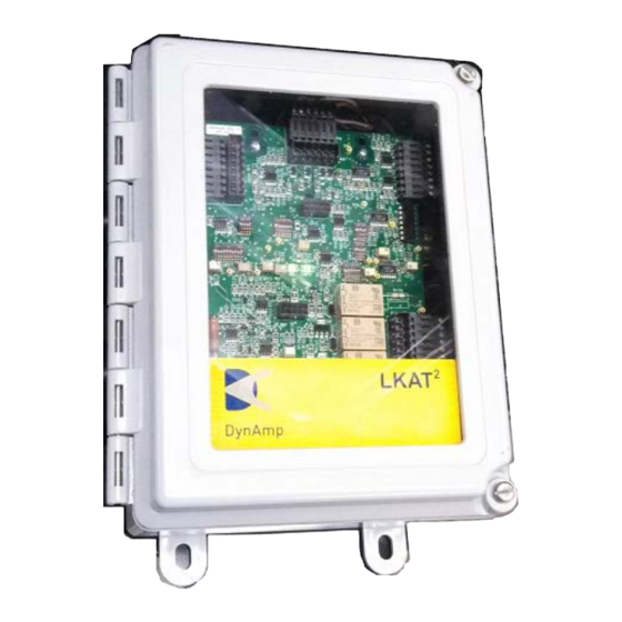
Internally, all LKAT Metering Units include both a Power Supply pc board and a Main pc board. These 2 PC boards are mounted to a steel chassis which is then mounted on a steel © 2018 DynAmp, LLC Page 6 047312 A... -
Page 21: Additional Indicator And Output Detail
Checking field calibration of LKAT Systems requires use of a reference current transducer with calibration accuracy of 0.1% full-scale or better. Contact DynAmp, LLC for calibration of the LKAT System. Refer to “Maintenance and Spare Parts” section for more information. -
Page 22: Mains Power Cable Assembly Detail
The unused conductors may be trimmed flush to cable jacket. The user may install ferrules or lugs on the stripped wire ends of the cable. These should be appropriate for connection to the appropriate inputs during use. © 2018 DynAmp, LLC Page 8 047312 A... -
Page 23: Specifications
All Relay Function Form C : Normally Open and Normally Closed Contacts ( non-latching ) All Relay Contact Ratings 120/250 VAC : 8A 30 VDC : 8A Relay response time 10mS typical © 2018 DynAmp, LLC Page 9 047312 A... - Page 24 Operating Ambient Temperature Range of -20°C to 80°C Measuring Head (-4°F to 176°F) Environmental rating: Measuring Head and cable IP65 connection at Head Environmental rating: Metering Unit and cable IP65 connection at Metering Unit © 2018 DynAmp, LLC Page 10 047312 A...
- Page 25 Normalized Frequency f/fc ; fc = 1 1 2 .4 x 10 ( A / s ) / I F S ( A ) F.S. Bus Current (kA) 5 to 50 Corner Frequency (kHz) 2.248 1.873 1.606 1.405 1.249 1.124 © 2018 DynAmp, LLC Page 11 047312 A...
- Page 26 LKAT Portable Installation, Operation and Service Manual This Page is Intentionally Blank © 2018 DynAmp, LLC Page 12 047312 A...
-
Page 27: Installation
The complete system should be inspected for shipping damage at the earliest opportunity. Visible damage must be reported to the carrier immediately. Concealed damage (not evident until the system is operated) must be reported to DynAmp, LLC immediately. INSTALLATION CONSIDERATIONS Read the following before mounting the head: 1. -
Page 28: Off-Bus Functional Check (Optional)
Diagnostic Measurements Form 1– Zero Primary Current” and contact the factory. Refer to “LKAT2 Diagnostic Measurements Form 1 – Zero Primary Current”. Allow the system one hour to stabilize prior to making measurements. Make measurements and record data shown on the form. File the completed test form for future reference. It is OK to... - Page 29 6. Connect the ITC Cable assembly to the Metering Unit. INSTALLATION USING MOUNTING CHANNELS Refer to the Outline and Mounting LKAT2 4-pc Measuring Head drawing at the end of this manual. The mounting hardware for this method consists of appropriately sized fiberglass channels and rods along with brass washers and nuts.
-
Page 30: Metering Unit
SYSTEM CHECKOUT Recheck all wiring connections against the drawings to ensure proper installation. Energize the LKAT2 System. Confirm that the green status LEDs are illuminated. If accuracy diagnostic LED lights red, skip to “Troubleshooting an Accuracy Diagnostics Fault Indication” in the “Theory of Operation” section of this manual Energize the rectifier to the desired test current. - Page 31 Portable Installation, Operation and Service Manual Photocopy the appropriate LKAT2 Diagnostic Measurements Forms. Form 1 is for diagnostic measurements at zero bus current (with the Measuring Head on or off the bus). Form 2 is for diagnostic measurements with the Measuring Head installed on the bus with the bus energized.
- Page 32 P2-3 P2-2 (±5mV) Output Current P3-1 P3-2 10.2V Loop Burden at Full-Scale Serial Numbers : Metering Unit ___________________ Measuring Head - A1 _______________ B1 _______________ Measuring Head - A2 _______________ B2 _______________ © 2018 DynAmp, LLC Page 18 047312 A...
- Page 33 P3-2 Loop Burden at Full-Scale Serial Numbers : Metering Unit ___________________ Measuring Head - A1 _______________ B1 _______________ Measuring Head - A2 _______________ B2 _______________ Nominal Current Loop Burden Resistance (Ohms) _________ © 2018 DynAmp, LLC Page 19 047312 A...
- Page 34 LKAT Portable Installation, Operation and Service Manual This Page is Intentionally Blank © 2018 DynAmp, LLC Page 20 047312 A...
-
Page 35: Theory Of Operation
The absence of a magnetic core practically eliminates errors due to saturation, hysteresis, and core set (remanence) commonly associated with ferrite material. A generalized block diagram of the LKAT System is shown in Figure 5.1. © 2018 DynAmp, LLC Page 21 047312 A... -
Page 36: System Functional Description
LED will go out and the red LED will illuminate. The relay coil will change state under the same conditions. The Trip Setpoint LEDs and relay contacts operate in a similar manner. © 2018 DynAmp, LLC Page 22 047312 A... -
Page 37: Lkat Metering Unit
This is true whether or not the Measuring Head is installed on the bus. The following table is intended to help the user determine and eliminate the cause of the fault. © 2018 DynAmp, LLC Page 23 047312 A... -
Page 38: System Calibration Overview
Laboratory Accreditation Bureau "Guidance for Documenting and Implementing ISO/IEC 17025:2005 and Laboratory Guidance." As a guideline, DynAmp recommends a 24-month interval of calibration for all permanently installed products and a 12-month interval of calibration for all products used in portable applications. -
Page 39: Calibration Adjustments
Field calibration is possible using a 0.1% accurate current measurement system, such as the DynAmp LKP, LKCO or Opti-Cal as a reference. Due to significantly larger size and mass, it may be difficult to install a comparably rated LKP Measuring Head in on the same bus as the LKAT . -
Page 40: Field Configuration Of Trip Setpoints
The trip setpoint is proportional to the current where the trip will occur: “Trip Current” – from Metering Unit nameplate. The easiest method to check or change trip setpoints is to use the DynAmp LKAT MUT system which is specifically designed to simplify this process as well as verify proper operation afterwards. - Page 41 LKAT Metering Unit nameplate will no longer be correct. In this case, DynAmp suggests that the nameplate be changed to reflect the new trip setpoint (following reconfiguration). © 2018 DynAmp, LLC...
-
Page 42: Earth Grounding
Here is a detailed description of the Earth Ground connection path: 1. The input power cable assembly connects CONN4 to the mains power. 2. Refer to the LKAT2 System Wiring Diagram and wire accordingly. 3. The earth ground wire connects from CONN4 to the FLTR1 metal case only. The FLTR1 metal enclosure is not connected to copper foil traces on the Power Supply PC Board Assembly, the steel standoff inserts or the steel PCB mounting bracket. -
Page 43: Maintenance & Spare Parts
PERIODIC MAINTENANCE As is true with any electronic system, proper maintenance will tend to prolong the service life. DynAmp, LLC recommends the following program be performed at the recommended interval to prevent or detect damage to the LKAT System and to ensure reliable performance. -
Page 44: Spare Parts
System Measuring Heads require special repair procedures and materials. However, the heads are very reliable and should require little or no repair over its service life. Please refer to the nearest authorized DynAmp, LLC service center for information on repairs. -
Page 45: Drawings
4PC Measuring Head Mounting 02B109566 Channels _ Running Bus Bar Configuration Outline and Mounting: LKAT Metering Unit Enclosure 02B109280 Outline and Mounting: LKAT P Instrument Output Cable 02B109567 Assembly Case, Travel 13B046980 © 2018 DynAmp, LLC Page 31 047312 A...
Need help?
Do you have a question about the LKAT2 and is the answer not in the manual?
Questions and answers