Table of Contents

Subscribe to Our Youtube Channel
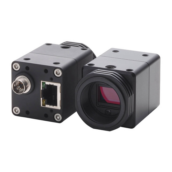
Related Manuals for Omron STC-MBS1242POE


Summary of Contents for Omron STC-MBS1242POE
- Page 1 No.18S052-02 GigE Vision Monochrome / Color CMOS PoE Camera STC-MBS1242POE Monochrome (12M / STC-MCS1242POE Color (12M / Product Specifications and User’s Guide STC-MBS1242POE / STC-MCS1242POE 1/72 Product Specifications and User’s Guide...
-
Page 2: Table Of Contents
Naming Method ........................10 Specifications ...................... 11 Electronic Specifications ....................... 11 Spectral Sensitivity Characteristics ..................13 STC-MBS1242POE .......................... 13 STC-MCS1242POE (without IR Cut Filter) ..................13 IR Cut Filter (STC-MCS1242POE) ....................14 Mechanical Specifications ..................... 14 Environmental Specifications ....................15 Connector Specifications .................. - Page 3 No.18S052-02 Dimensions ......................27 STC-MBS1242POE ......................... 27 STC-MCS1242POE ......................... 28 Sensor Information .................... 29 Pixel Transferring Image ......................29 Camera Operational Modes ................30 Normal Mode (Rolling shutter) ....................30 Pulse width trigger mode....................... 31 Timing (when using rolling shutter) ....................31 Exposure Timing with Positive Polarity Trigger Signal ..............
- Page 4 Action Control ........................55 10.21 IEEE1588 ........................... 56 GenICam command .................... 58 11.1 DeviceControl ........................58 11.2 ImageFormatControl ......................60 11.3 AcquisitionControl ......................61 11.4 AnalogControl ........................62 11.5 LUTControl ........................... 63 STC-MBS1242POE / STC-MCS1242POE 4/72 Product Specifications and User’s Guide...
- Page 5 11.10 EventControl ........................66 11.11 UserSetControl ........................66 11.12 ChunkDataControl ....................... 67 11.13 ActionControl ........................67 11.14 File AccessControl ......................68 11.15 TestControl .......................... 68 11.16 TransportLayerControl ....................... 69 12 Revision History ....................71 STC-MBS1242POE / STC-MCS1242POE 5/72 Product Specifications and User’s Guide...
- Page 6 Do not use with out of power voltage range Do not wrong wiring. that is specified in the specifications for this This will cause of fire or malfunction. camera. This will cause of fire, electrification or malfunction. STC-MBS1242POE / STC-MCS1242POE 6/72 Product Specifications and User’s Guide...
- Page 7 It is turn off the camera when maintaining or This will cause of fire, electrification or inspecting the camera. malfunction. This will cause of electrification. [Disposal] Caution It is necessary to dispose as industrial waste. STC-MBS1242POE / STC-MCS1242POE 7/72 Product Specifications and User’s Guide...
-
Page 8: Product Precautions
Exchange or repair the malfunction camera if the malfunction is occurred by our responsibility. “Warranty” mean is warranty for the delivered camera itself. Please accept the induction damage by the camera malfunction is not included. STC-MBS1242POE / STC-MCS1242POE 8/72 Product Specifications and User’s Guide... -
Page 9: Software Licensing
BUSINESS INTERRUPTION) HOWEVER CAUSED AND ON ANY THEORY OF LIABILITY, WHETHER IN CONTRACT, STRICT LIABILITY, OR TORT (INCLUDING NEGLIGENCE OR OTHERWISE) ARISING IN ANY WAY OUT OF THE USE OF THIS SOFTWARE, EVEN IF ADVISED OF THE POSSIBILITY OF SUCH DAMAGE. STC-MBS1242POE / STC-MCS1242POE 9/72 Product Specifications and User’s Guide... -
Page 10: Introduction
No.18S052-02 Introduction This document describes the specification of the following cameras: STC-MBS1242POE / STC-MCS1242POE Features GigE Interface Support PoE (Power over Ethernet) Small robust camera housing Maximum frame rate (Full resolution): 9.2 fps @ 12M 8bits ... -
Page 11: Specifications
Input Voltage (*4) +10.8 to +26.4 Vdc External power (via 6 pin connector) / Power Over Ethernet (IEEE802.3af) Consumption +12 V / +24 V: 3.3 W, PoE: 4.0 W Default: Bold STC-MBS1242POE / STC-MCS1242POE 11/72 Product Specifications and User’s Guide... - Page 12 (*3) The exposure time range for RGB8 pixel format is 423 μseconds to 16.777 seconds. (*4) The camera operates with external power when power suppling by external power supply and PoE to camera at same time. STC-MBS1242POE / STC-MCS1242POE 12/72 Product Specifications and User’s Guide...
-
Page 13: Spectral Sensitivity Characteristics
No.18S052-02 Spectral Sensitivity Characteristics STC-MBS1242POE STC-MCS1242POE (without IR Cut Filter) STC-MBS1242POE / STC-MCS1242POE 13/72 Product Specifications and User’s Guide... -
Page 14: Ir Cut Filter (Stc-Mcs1242Poe)
Ethernet connector: RJ45 connector Power- I/O connector: HR10A-7R-6PB (Hirose) or equivalent Camera Mounting Six M3 screw holes (Two on top, four on bottom plate) Weight Approximately 65 g (*1) Excluding the connectors STC-MBS1242POE / STC-MCS1242POE 14/72 Product Specifications and User’s Guide... -
Page 15: Environmental Specifications
72 deg. C, the camera housing temperature (top plate) will be less than 61 deg. C. Taking these steps will maintain the heat rating of the electronic components of the camera. Upper side of camera Measuring point STC-MBS1242POE / STC-MCS1242POE 15/72 Product Specifications and User’s Guide... -
Page 16: Connector Specifications
Yellow light: Blinking 1 GB Transferring 100 MB Transferring Please use a 1GB supported NIC, Network Switcher and Ethernet cable. Check the setting of NIC and Network Switcher being used is “1GB transferring”. STC-MBS1242POE / STC-MCS1242POE 16/72 Product Specifications and User’s Guide... -
Page 17: Power And Control Signal Connector
9) User Output 1 10) User Output 2 11) Timer 0 Active 12) Software Signal 0 13) Software Signal 1 14) Logic Block 0 15) Pulse Per Second 16) Flash Window STC-MBS1242POE / STC-MCS1242POE 17/72 Product Specifications and User’s Guide... - Page 18 Selected signal for “Software Signal 1” at “Software Signal Control” is out. 14) Logic Block 0 “Logic Block 0” signal is out. 15) Pulse Per Second “Pulse / second” signal (50% Duty, 1 Hz interval) is out. STC-MBS1242POE / STC-MCS1242POE 18/72 Product Specifications and User’s Guide...
- Page 19 This signal can be used to set active time of light source for rolling shutter to acquire acceptable image. Line0 Line0 Line1 Line1 Line2 Line2 LineN-1 LineN-1 LineN LineN Rolling shutter Global Reset shutter STC-MBS1242POE / STC-MCS1242POE 19/72 Product Specifications and User’s Guide...
-
Page 20: Opto-Isolated Input
The camera has current limiting circuit on camera. The current limiting resistor does not necessary. Opto-isolated output It is necessary to have current limiting resistor at outside of camera, to keep less than 50 mA. STC-MBS1242POE / STC-MCS1242POE 20/72 Product Specifications and User’s Guide... -
Page 21: Open Collector Gpio
The camera inside circuit may get damage if accidentally uses as output without current limiting resistor. For safety, please add current limiting resistor even use as input. a) Open Collector GPIO uses as output b) Open Collector GIPO uses as input STC-MBS1242POE / STC-MCS1242POE 21/72 Product Specifications and User’s Guide... -
Page 22: Input And Output Signal Timing (Hardware Trigger)
ExposureActive DebounceLine0, 2 FramTriggerInternal SensorReadOut Timer0 Parameter TimerDelay on GenICam Parameter TimerDuration on GenICam (*1) Please refers “5.2.6 External Hardware Trigger Input Delay” for more details about “External hardware trigger delay” STC-MBS1242POE / STC-MCS1242POE 22/72 Product Specifications and User’s Guide... -
Page 23: Input And Output Signal Timing (Software Trigger)
Trigger delay Line 1 Line 2 Exposure Line N-1 Line N Parameter ExposureTime on GenICam Image out Output signals FrameTriggerWait ExposureActive FramTriggerInternal SensorReadOut Timer0 Parameter TimerDelay on GenICam Parameter TimerDuration on GenICam STC-MBS1242POE / STC-MCS1242POE 23/72 Product Specifications and User’s Guide... -
Page 24: External Hardware Trigger Input Delay
External Trigger Signal External Trigger Signal with camera internal delay Tdelay 6.2.6.2 External Trigger Signal Delay (Negative polarity trigger signal) External Trigger Signal External Trigger Signal with camera internal delay Tdelay STC-MBS1242POE / STC-MCS1242POE 24/72 Product Specifications and User’s Guide... -
Page 25: Measured External Trigger Signal Delay Through Opt-Isolated Port (Line 0)
2 μseconds +24 V 53.2 μseconds 2 μseconds Note. Please use this measured delay as reference. The delay time may fluctuate depending on photo coupler variation, pull-up voltage and pull-up resister. STC-MBS1242POE / STC-MCS1242POE 25/72 Product Specifications and User’s Guide... -
Page 26: Measured External Trigger Signal Delay Through Open Collector Gpio Port (Line 2)
2.2 μseconds 2 μseconds +24 V 0.8 μseconds 2 μseconds Note. Please use this measured delay as reference. The delay time may fluctuate depending on transistor variation, pull-up voltage and pull-up resister. STC-MBS1242POE / STC-MCS1242POE 26/72 Product Specifications and User’s Guide... -
Page 27: Dimensions
No.18S052-02 Dimensions STC-MBS1242POE 2-M3 Depth3.5 2-M2 Depth4 1”-32UNF (C mount) 4-M3 Depth3.5 Unit: mm STC-MBS1242POE / STC-MCS1242POE 27/72 Product Specifications and User’s Guide... -
Page 28: Stc-Mcs1242Poe
No.18S052-02 STC-MCS1242POE 2-M3 Depth3.5 2-M2 Depth4 1”-32UNF (C mount) 4-M3 Depth3.5 Unit: mm STC-MBS1242POE / STC-MCS1242POE 28/72 Product Specifications and User’s Guide... -
Page 29: Sensor Information
Pixel (m) of Data: mth pixel being transferred STC-MCS1242POE (Color) Pixel11 of Pixel12 of Data Data Pixe21 of Pixel22 of Data Data Pixel (m, n) of Data: mth pixel of nth line being transferred STC-MBS1242POE / STC-MCS1242POE 29/72 Product Specifications and User’s Guide... -
Page 30: Camera Operational Modes
Line 2 Line 2 Exposure Line N-1 Line N-1 Line N-1 Line N-1 Line N Line N Line N Line N Image out * The exposure time for each line is same. STC-MBS1242POE / STC-MCS1242POE 30/72 Product Specifications and User’s Guide... -
Page 31: Pulse Width Trigger Mode
(Positive polarity) Exposure Line 1 Exposure Line 2 Exposure Line N Image out Note: The exposure time is active pulse duration of trigger signal. Please refers “Exposure Timing” for more details. STC-MBS1242POE / STC-MCS1242POE 31/72 Product Specifications and User’s Guide... -
Page 32: Exposure Timing With Positive Polarity Trigger Signal
Note 2: Please refers “5.2.6 External Hardware Trigger Input Delay” for more details about “External hardware trigger delay”. Note 3: Please refers “5.2.6 External Hardware Trigger Input Delay” for shortest active pulse duration of trigger signal. STC-MBS1242POE / STC-MCS1242POE 32/72 Product Specifications and User’s Guide... -
Page 33: Exposure Timing With Negative Polarity Trigger Signal
Note 2: Please refers “5.2.6 External Hardware Trigger Input Delay” for more details about “External hardware trigger delay”. Note 3: Please refers “5.2.6 External Hardware Trigger Input Delay” for shortest active pulse duration of trigger signal. STC-MBS1242POE / STC-MCS1242POE 33/72 Product Specifications and User’s Guide... -
Page 34: Edge Preset Trigger Mode
Timing (When using rolling shutter) Trigger signal (Positive polarity) Exposure Line 1 Exposure Line 1 Exposure Line N Image out Note: The exposure time is “Exposure Time” on GenICam setting. STC-MBS1242POE / STC-MCS1242POE 34/72 Product Specifications and User’s Guide... -
Page 35: Exposure Timing With Positive Polarity Trigger Signal
“Line Debounce Time” setting time. Please input trigger signal has more than “Line Debounce Time” time active pulse width trigger signal. Note 2: Please refers “5.2.6 External Hardware Trigger Input Delay” for more details about “External hardware trigger delay”. STC-MBS1242POE / STC-MCS1242POE 35/72 Product Specifications and User’s Guide... -
Page 36: Edge Preset Trigger Mode (Trigger Input While Image Is Out)
However, if the trigger signal input while exposing with previous trigger signal or output image, trigger signal is disregard. Timing Trigger signal (Positive polarity) Exposure Image out Note: The exposure time is “Exposure Time” on GenICam setting. STC-MBS1242POE / STC-MCS1242POE 36/72 Product Specifications and User’s Guide... -
Page 37: 10 Camera Functions
“User Set Save” CANNOT execute when “Default” was selected at “User Set Selector” User Set Selector Setting Procedure 1. Selects “User Set X” at “User Set Selector” 2. Execute “User Set Save” STC-MBS1242POE / STC-MCS1242POE 37/72 Product Specifications and User’s Guide... -
Page 38: Loading Camera Settings
Please follow the procedure in below for camera settings put back to factory default settings. Setting Procedure Selects “Default” at “User Set Selector”. Executes “User Set Load”. Select “User Set X” at “User Set Selector”. Executes “User Set Save”. STC-MBS1242POE / STC-MCS1242POE 38/72 Product Specifications and User’s Guide... -
Page 39: Frame Rate
Selects control gain Digital All: Digital Gain DigitalGain IFloat Type Digital Gain Range: 0 to 255 Default: 0 Digital Gain Formula Gain (x times) = 1 + (“Digital Gain” / 128) STC-MBS1242POE / STC-MCS1242POE 39/72 Product Specifications and User’s Guide... -
Page 40: Exposure Time
The lower limit of signal is clamped at this setting level. The signal does not lower than this. GenICam Parameters BlackLevel IFloat Type Black Level Range: 12bits output: 0 to 252 10bits output: 0 to 63 8bits output: 0 to 15 Default: 0 STC-MBS1242POE / STC-MCS1242POE 40/72 Product Specifications and User’s Guide... -
Page 41: Alc (Auto Light Control)
Default: 1 * Sets 10 on Region 4 only Sets the weight for each weight area. AutoLuminancePeak IInteger Type Importance ratio for the brightness peak at ALC control. Range: 0 to 255 Default: 0 STC-MBS1242POE / STC-MCS1242POE 41/72 Product Specifications and User’s Guide... -
Page 42: Alc Control Method
If AGC and auto shutter are ON for ALC control, auto shutter function maintains brightness first. The AGC function maintains brightness if brightness cannot maintain to “Auto Luminance Target” with auto shutter. STC-MBS1242POE / STC-MCS1242POE 42/72 Product Specifications and User’s Guide... -
Page 43: Agc (Auto Gain Contorl)
This cannot be set greater than “Gain Auto Limit Max” GainAutoLimitMax IFloat Type Maximum gain for AGC [GainSelector] Range: 0 to 212 Default: 212 This cannot be set smaller than “Gain Auto Limit Min” STC-MBS1242POE / STC-MCS1242POE 43/72 Product Specifications and User’s Guide... -
Page 44: Auto Shutter
4. Sets “Continuous” for “Exposure Auto” when using auto shutter function. 5. Sets “Exposure Auto Limit Min” and “Exposure Auto Limit Max” when using auto shutter function. 6. Sets “Auto Luminance Target”. STC-MBS1242POE / STC-MCS1242POE 44/72 Product Specifications and User’s Guide... -
Page 45: White Balance (Only Available For Color Camera)
Sets “OFF” at “Balance White Auto” automatically after sets “Balance Ratio” for all colors. Push to set white balance setting procedure 1. Sets the flat white target then acquires image. 2. Sets “Once” at “Balance White Auto”. STC-MBS1242POE / STC-MCS1242POE 45/72 Product Specifications and User’s Guide... -
Page 46: White Balance Calculate Region Setting
Vertical offset (in line) for region 0 YOffset Range: 0 to 2,999 Default: 0 The white balance calculation region settings are like below: BalanceWhite AutoOffsetY White balance gain BalanceWhite calculation region 0 AutoHeight BalanceWhite BalanceWhite AutoOffsetX AutoWidth STC-MBS1242POE / STC-MCS1242POE 46/72 Product Specifications and User’s Guide... -
Page 47: Gamma Correction
OffsetY IInteger Type Vertical offset for output image (in line) Range: 0 to 2,998 Default: 0 Adjustable steps: 2 The ROI region settings are below: OffsetY Height ROI region OffsetX Width STC-MBS1242POE / STC-MCS1242POE 47/72 Product Specifications and User’s Guide... -
Page 48: Sensor Height Limitation
Mono10 Mono10 BayerRG10 10bits Packed Mono10Packed Mono10Packed BayerRG10Packed 12bits Mono12 Mono12 BayerRG12 12bits Packed Mono12Packed Mono12Packed BayerRG12Packed 8bits x 3 RGB8 Each format specified on GenICam PFNC (Pixel Format Naming Convention). STC-MBS1242POE / STC-MCS1242POE 48/72 Product Specifications and User’s Guide... -
Page 49: Precautions For Stc-Sbs1242Poe
IEnumeration Type Pixel position High Left High Right Low Left Low Right GainBalanceRatio IInteger Type Gain for “Gain Auto Balance” (Once) GainBalanceRatio IInteger Type Gain for “Gain Auto Balance” (Preset) PresetRaw STC-MBS1242POE / STC-MCS1242POE 49/72 Product Specifications and User’s Guide... -
Page 50: Trigger
Action 0 Trigger Delay Timing Generator Software Signal 0 Software Signal 1 Sensor Logic Block 0 Trigger Source The trigger signal is selectable by GenICam commands. Trigger Source: select trigger type STC-MBS1242POE / STC-MCS1242POE 50/72 Product Specifications and User’s Guide... -
Page 51: Image Flip
Range: 0 to 4,095 LUT Value IInteger Type The output value for input value that specifies by index Range: 0 to 4,095 4095 4095 LUT Index e.g. LUT usage (low brightness level enhancement) STC-MBS1242POE / STC-MCS1242POE 51/72 Product Specifications and User’s Guide... -
Page 52: Defective Pixel Correction
Horizontal position for selected index for process defective pixel correction Range: 0 to 3,999 Default: 0 PixelCorrectionY IInteger Type Vertical position for selected index for process defective pixel correction Range: 0 to 2,999 Default: 0 STC-MBS1242POE / STC-MCS1242POE 52/72 Product Specifications and User’s Guide... -
Page 53: Counter And Timer Control
IEnumeration Type Polarity of reference signal to reset counter Activation CounterReset ICommand Type Rest switch “Activate as switch when selecting “Software” at “Counter Reset Source” CounterValue IInteger Type Returns number of counter STC-MBS1242POE / STC-MCS1242POE 53/72 Product Specifications and User’s Guide... -
Page 54: E.g. Event Control
“Line 0 Input Rising Edge”, “Line 0 Input Falling Edge”, “Line 2 Input Rising Edge” and “Line 2 Input Falling Edge” Event Notification IEnumeration Type Event notification ON / OFF selection On: Enable event notification Off: Disable event notification STC-MBS1242POE / STC-MCS1242POE 54/72 Product Specifications and User’s Guide... -
Page 55: Chunk Control
IInteger Type Select camera to apply action command Logical AND of Group Mask of camera and Group Mask of action command is 1 for any bit of 32bits, camera executes action command. STC-MBS1242POE / STC-MCS1242POE 55/72 Product Specifications and User’s Guide... -
Page 56: Ieee1588
Defined delay between master device and slave device by comparing these messages. If time difference between master device and slave device is occurred, adjust internal clock of slave device to synchronize to master device. Synchronize clock regularly to correcting time drift. STC-MBS1242POE / STC-MCS1242POE 56/72 Product Specifications and User’s Guide... - Page 57 Timestamp, action command will be scheduled automatically and each camera start exposing at same time. Action Control setting is required when action command generating. IEEE1588 PTP supported Switching HUB M: Master S: Slave e.g. PTP configuration STC-MBS1242POE / STC-MCS1242POE 57/72 Product Specifications and User’s Guide...
-
Page 58: 11 Genicam Command
Maximum bandwidth of the data that can be streamed out of the device. DeviceLinkSelector Selects which Link of the device to control. DeviceLinkSpeed Indicates the speed of transmission negotiated on the specified Link. [DeviceLinkSelector] STC-MBS1242POE / STC-MCS1242POE 58/72 Product Specifications and User’s Guide... - Page 59 Latches the current timestamp counter into Timestamp Latch Value. TimestampLatchValue Returns the latched value of the timestamp counter. DeviceUserMemory Read / Write the user data from / to the non-volatile memory. STC-MBS1242POE / STC-MCS1242POE 59/72 Product Specifications and User’s Guide...
-
Page 60: Imageformatcontrol
Selects which test pattern generator is controlled by the Test Pattern feature. TestPattern Selects the type of test pattern that is generated by the device as [TestPatternGeneratorSelector] image source. TestPatternInputValue Test Pattern Input Value [TestPatternGeneratorSelector] STC-MBS1242POE / STC-MCS1242POE 60/72 Product Specifications and User’s Guide... -
Page 61: Acquisitioncontrol
Sets the automatic exposure mode when Exposure Mode is Timed. ExposureAutoLimitMin Determine the lower limit of exposure time when Exposure Auto is set to Continuous. ExposureAutoLimitMax Determine the upper limit of exposure time when Exposure Auto is set to Continuous. STC-MBS1242POE / STC-MCS1242POE 61/72 Product Specifications and User’s Guide... -
Page 62: Analogcontrol
Determine X offset of targeted region for auto white balance. [BalanceWhiteAuto RegionSelector] (STC-MCS1242POE) BalanceWhiteAutoOffsetY Determine Y offset of targeted region for auto white balance. [BalanceWhiteAutoRegionSelector] (STC-MCS1242POE) Gamma Controls the gamma correction of pixel intensity. STC-MBS1242POE / STC-MCS1242POE 62/72 Product Specifications and User’s Guide... -
Page 63: Lutcontrol
Sets the mode for automatic gain balancing between the sensor color channels or taps. The gain coefficients of each channel or tap are adjusted so they are matched. (STC-MBS1242POE) GainBalanceSelector Selects the position for gain balance. (STC-MBS1242POE) GainBalanceRatioRaw Determine value of targeted position for gain balance. [GainBalanceSelector]... -
Page 64: Digitaliocontrol
Selects if the selected Logic Block Input source signal is inverted. [LogicBlockSelector] [LogicBlockInputSelector] SoftwareSignalControl 11.8 Name Description SoftwareSignalSelector Selects which Software Signal features to control. SoftwareSignalPulse Generates a pulse signal that can be used as a software trigger. [SoftwareSignalSelector] STC-MBS1242POE / STC-MCS1242POE 64/72 Product Specifications and User’s Guide... -
Page 65: Counterandtimercontrol
Selects the source of the trigger to start the Timer. TimerTriggerActivation [TimerSelector] Selects the activation mode of the trigger to start the Timer. TimerValue [TimerSelector] Reads or writes the current value (in microseconds) of the selected Timer. STC-MBS1242POE / STC-MCS1242POE 65/72 Product Specifications and User’s Guide... -
Page 66: Eventcontrol
Save the User Set specified by User Set Selector to the non-volatile memory of the device. UserSetDefault Selects the feature User Set to load and make active by default when the device is reset. STC-MBS1242POE / STC-MCS1242POE 66/72 Product Specifications and User’s Guide... -
Page 67: Chunkdatacontrol
Provides the mask that the device will use to validate the action on reception of the action protocol message. ActionGroupKey [ActionSelector] Provides the key that the device will use to validate the action on reception of the action protocol message. STC-MBS1242POE / STC-MCS1242POE 67/72 Product Specifications and User’s Guide... -
Page 68: File Accesscontrol
Represents the file operation result. [FileSelector] [FileOperationSelector] FileSize [FileSelector] Represents the size of the selected file in bytes. TestControl 11.15 Name Description TestPendingAck Tests the device's pending acknowledge feature. TestEventGenerate Generates a Test Event. STC-MBS1242POE / STC-MCS1242POE 68/72 Product Specifications and User’s Guide... -
Page 69: Transportlayercontrol
Controls the Persistent subnet mask associated with the Persistent IP [GevInterfaceSelector] address on this logical link. GevPersistentDefaultGateway Controls the persistent default gateway for this logical link. [GevInterfaceSelector] GevGVCPExtendedStatusCodesSelector Selects the GigE Vision version to control extended status codes for. STC-MBS1242POE / STC-MCS1242POE 69/72 Product Specifications and User’s Guide... - Page 70 GVSP transmitter must send data stream or the destination IP address from which a GVSP receiver may receive data stream. GevSCSP [GevStreamChannelSelector] Indicates the source port of the stream channel. STC-MBS1242POE / STC-MCS1242POE 70/72 Product Specifications and User’s Guide...
-
Page 71: 12 Revision History
Added “LWIP TCP/IP Licensing” information GigE Vision is trademark of AIA. GenICam is trademark of EMVA. Other company names and product names in this document are trademarks of their respective owners. STC-MBS1242POE / STC-MCS1242POE 71/72 Product Specifications and User’s Guide... - Page 72 No.18S052-02 19F, Ebina Prime Tower 9-50, Chuo 2 chome Ebina-city, Kanagawa 243-0432 Japan TEL 81-46-236-6660 FAX 81-46-236-6661 URL http://www.sentech.co.jp/ STC-MBS1242POE / STC-MCS1242POE 72/72 Product Specifications and User’s Guide...
Need help?
Do you have a question about the STC-MBS1242POE and is the answer not in the manual?
Questions and answers