
Related Manuals for Parsun T40J BM


Summary of Contents for Parsun T40J BM
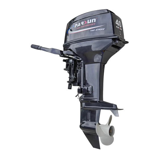
- Page 1 OUTBOARD MOTOR OWNER’S MANUAL T40J BM/BW/FW T40G BM/BW/FW SUZHOU PARSUN POWER MACHINE CO., LTD.
- Page 2 Thank you for owning a PARSUN outboard motor. Thank you for your trust in our company and products. “PARSUN” outboard motors are powerful, economic and safe with advanced technology and processing technique. Please read this manual carefully before operating your outboard motor. A thorough understanding of the manual will help you to know this product for proper operation, maintenance and care.
- Page 3 Record your outboard motor serial number in the spaces provided to assist you in ordering spare parts from your Parsun dealer, or for reference in case your outboard motor is stolen. 1. Outboard motor serial number location...
- Page 4 Engine serial number The engine serial number is carved on the aluminum casting of engine. Serial number as follows:...
-
Page 5: Table Of Contents
Table of contents 1. Main components and General information ..................... 1 1.1 Main components ............................1 1.2 General information ............................5 1.2.1 Specifications .............................. 5 1.2.2 Fueling instructions ............................. 6 1.2.3 Propeller selection ............................7 2. Operation ................................. 8 2.1 Installation ..............................8 2.1.1 Mounting height............................ - Page 6 2.9 Stopping engine ............................30 2.10 Trimming outboard motor ........................... 32 2.11 Tilting up and down ............................ 33 2.11.1 Tilting up ..............................34 2.11.2 Tilting down ............................. 36 2.12 Cruising in other conditions ........................36 2.12.1 Cruising in shallow water ........................36 3.
- Page 7 3.11 Checking top cowling ..........................50 3.12 Maintenance Table ............................. 51 4. Transporting and storing ..........................53 4.1 Transporting ..............................53 4.2 Storing ................................54 5. Actions in emergency ............................. 56 5.1 Impact damage ............................56 5.2 Starter will not operate ..........................56 5.3 Treatment of submerged motor ........................
-
Page 8: Main Components And General Information
1. Main components and General information 1.1 Main components 1. Throttle grip 7. Top cowling 13. Clamp screw 2. Tiller handle 8. Manual starter handle 14. Fuel joint 3. Cooling water inlet 9. choke knob 15. Fuel tank 4. Top cowling lock handle 10. - Page 9 If your model includes a portable fuel tank, its parts are as follows: Fuel tank cap 3. Air vent screw 2. Fuel joint 4. Fuel gauge WARNING: The fuel tank supplied with this engine could only be used as supply of fuel for its running and must not be as a fuel storage container.
- Page 10 Remote control lever Moving the lever forward from the neutral position engages forward gear. Pulling the lever back from neutral engages reverse. The engine will continue to run at idle until the lever is moved about 35º (a detent can be felt). Moving the lever farther opens the throttle, and the engine will begin to accelerate.
- Page 11 Neutral throttle lever To open the throttle without shifting into either forward or reverse, put the remote control lever in the neutral position and lift the neutral throttle lever. NOTE: The neutral throttle lever will operate only when the remote control lever is in neutral. The remote control lever will operate only when the neutral throttle lever is in the closed position 1.
-
Page 12: General Information
1.2 General information 1.2.1 Specifications Parameter Items Data Items Data Type of engine 2-stroke L Weight L (BM/FW) 67kg/70kg Displacement 669cm Transom S 381mm Bore X stroke 78mm×70mm Transom L 508mm Type J 2.00(26/13) Recommended fuel Unleaded regular gasoline Gear ratio Type G 1.85(24/13)... -
Page 13: Fueling Instructions
1.2.2 Fueling instructions Fueling instructions: Recommended gasoline: Regular unleaded gasoline, If it is not available, then premium gasoline. If knocking or pinging occurs, use a different brand of gasoline or premium unleaded fuel. If leaded gasoline is usually used, engine valves and related parts should be inspected after every 100 hours of operation. -
Page 14: Propeller Selection
CAUTION: Use only new clean gasoline which has been stored in clean containers and is not contaminated with water or foreign matter. Engine oil: Recommended engine oil: 2-stroke outboard motor oil Gasoline and oil mixing: 25:1 Break-in period Gasoline Engine oil 0.04L 0.48L 0.56L 0.96L 50:1 After break-in Gasoline... -
Page 15: Operation
“PARSUN” dealers stock a range of propellers and can advise you and install a propeller on your outboard that is best suited to your application. -
Page 16: Mounting Height
The optimum mounting height of the outboard motor is affected by the boat and motor combination and the desired use. Test runs at a different height can help determine the optimum mounting height. For further information, consult your "PARSUN" dealer or boat manufacturer. ~... -
Page 17: Clamping The Outboard Motor
2.1.2 Clamping the outboard motor 1. Tighten the transom clamp screw evenly and securely. Occasionally check the clamp screws for tightness during operation of the outboard motor because they could become loose due to engine vibration. CAUTION: Outboards that use clamp bracket screws alone are INSUFFICIENT to properly and safely secure the outboard to the Transom. -
Page 18: Breaking In Engine
3. Secure the clamp bracket to the transom using the appropriate bolts. For details, consult your PARSUN dealer. WARNING: Avoid using bolts, nuts or washers inappropriate. After tightening, test running the engine and check their tightness. 2.2 Breaking in engine Your new engine requires a period of break-in to allow mating surfaces of moving parts to wear in evenly. -
Page 19: Pre-Operation Checks
2. Next 50 minutes: Run the engine at 3000 r/min or at approximately half throttle. 3. Next 2 hours of operation: Run the engine at 4000 r/min or at approximately three-quarter throttle. 4. Next 7 hours of operation: Avoid continuous operation at full throttle for more than five minutes at a time. 5. -
Page 20: Filling Fuel
Check operation of the starter and stop switches when the outboard motor is in the water. Engine Check the engine and engine mounting. Look for loose or damaged fasteners. Check the propeller for damage. WARNING: If any item in the pre-operation check is not working properly, have it inspected and repaired before operating the outboard motor. -
Page 21: Starting Engine
2.5 Starting engine For BM model 1. Loosen the air vent screw on the fuel tank cap, 2 or 3 turns. 2. Connect fuel joints securely and squeeze the primer pump with the outlet end up until you feel it become firm (if equipped the fuel joint). - Page 22 WARNING: The engine must be started in neutral otherwise damage to the starter can occur. Do not attach the lanyard to clothing that could tear loose. Do not route the lanyard where it could become entangled, preventing it from functioning. ...
- Page 23 NOTE: The start-in-gear protection device prevents the engine from starting except when in neutral. Attach the engine stop switch lanyard to secure place on your clothing, or your arm or leg. Then install the lock plate on the other end of the lanyard into the engine stop switch. 4.
- Page 24 NOTE: It is not necessary to use the choke when starting a warm engine. If the choke is left in the “START” (start) position while the engine is running, the engine will run poorly or stall. 6. Pull the manual starter handle slowly until you feel resistance. Then give a strong pull straight to crank and start the engine.
- Page 25 For BW model 1. Connect fuel joints securely after loosen the air vent screw on the fuel tank cap (2 or 3 turns). 2. Connect fuel joints securely and squeeze the primer pump with the outlet end up until you feel it become firm (if equipped the fuel joint).
- Page 26 NOTE: The start-in-gear protection device prevents the engine from starting except when in neutral. Attach the engine stop switch lanyard to secure place on your clothing, or your arm or leg. Then install the lock plate on the other end of the lanyard into the engine stop switch. WARNING:...
- Page 27 4. Place the throttle grip in the “START”(start)position. Turn the main switch to “ON”(on). START 5.Turn the main switch to “START” (start), and hold it for a maximum or 5 seconds. START 6.After the engine starts, slowly return the manual starter handle to its original position before releasing it. Immediately after the engine starts, release the main switch and allow it to return to “ON”(on).
- Page 28 NOTE: Never turn the main switch to “START”(start)while the engine is running. Do not keep the starter motor turning for more than 5 seconds. If the starter motor is turned continuously for more than 5 seconds, the battery will be quickly discharged, thus making it impossible to start the engine.
- Page 29 3. Place the remote control lever in neutral. WARNING: The engine must be started in neutral otherwise damage to the starter can occur. Do not attach the lanyard to clothing that could tear loose. Do not route the lanyard where it could become entangled, preventing it from functioning.
- Page 30 4. Turn the main switch to “ON”(on). 5. Open the throttle slightly without shifting using the neutral throttle lever or free accelerator. You may need to change the throttle opening slightly depending on engine temperature. After the engine starts, return the throttle to the original position.
- Page 31 8.Slowly return the throttle grip to the fully closed position. NOTE: Never turn the main switch to “START” (start) while the engine is running. Do not keep the starter motor turning for more than 5 seconds. If the starter motor is turned continuously for more than 5 seconds, the battery will be quickly discharged, thus making it impossible to start the engine.
-
Page 32: Warming Up Engine
2.6 Warming up engine 1. After starting the engine, allow it to idle for 3 minutes to warm up. Failure to do so will shorten engine life. Gradually return the choke knob to its home position as the engine warms up. 2. -
Page 33: Shifting
2.7 Shifting WARNING: Before shifting, make sure there are no swimmers or obstacles in the water near you. CAUTION: To shift from forward to reverse or vice versa, first close the throttle so that the engine idles (or runs at low speeds). -
Page 34: Reverse
For FW Pull up the neutral interlock rigger and move the remote control lever quickly and firmly from neutral to forward. 2.7.2 Reverse WARNING: When operating in reverse, go slowly. Do not open the throttle more than half. Otherwise the boat could become unstable, which could result in loss of control and an accident. -
Page 35: Tiller
2. Move the gear shift lever quickly and firmly from neutral to reverse. NOTE: Make sure the tilt lock lever is in the lock/down position. For FW Pull up the neutral interlock rigger and move the remote control lever quickly and firmly from neutral to reverse. 2.8 Tiller 1. - Page 36 3. Throttle indicator The throttle indicator is on the throttle grip. The fuel consumption curve on the throttle indicator shows the relative amount of fuel consumed for each throttle position. Choose the setting that offers the best performance and fuel economy for the desired operation. 1.
-
Page 37: Stopping Engine
WARNING: Do not over-tighten the friction adjuster. If there is too much resistance, it could be difficult to move throttle lever or grip, which could result in an accident. 2.9 Stopping engine NOTE: Before stopping the engine, first let it cool off for a few minutes at idle or low speed. Stopping the engine immediately after operating at high speed is not recommended. - Page 38 2. Tighten the air vent screw on the fuel tank cap. 3. Disconnect the fuel line if you are using an external fuel tank. For FW 1. Turn the main switch to “OFF” (off). 2. Tighten the air vent screw on the fuel tank cap.
-
Page 39: Trimming Outboard Motor
3. Disconnect the fuel line. 2.10 Trimming outboard motor There are 4 or 5 holes provided in the clamp bracket to adjust the outboard motor trim angle. 1. Stop the engine. 2. Remove the trim rod from the clamp bracket hole slightly tilting the outboard motor up. -
Page 40: Tilting Up And Down
WARNING: Stop the engine before adjusting the trim angle. Use care to avoid being pinched when removing or installing the rod. Use caution when trying a trim position for the first time. Increase speed gradually and watch for any signs of instability or control problems. -
Page 41: Tilting Up
2.11.1 Tilting up 1. Place the gear shift lever in neutral (if equipped) and face the outboard motor forward. 2. Tighten the steering friction adjuster by turning it clockwise to prevent the motor from turning freely. 3. Tighten the air vent screw. Disconnect the fuel joint from the outboard motor. - Page 42 4. Place the tilt lock lever (if equipped) in the up position. 5. Hold the rear handle and tilt the engine up fully until the tilt support lever automatically locks.
-
Page 43: Tilting Down
2.11.2 Tilting down 1. Slightly tilt the outboard motor up. 2. Om models equipped with atilt support lever return it to the release position. 3. Slowly tilt the outboard motor down. 4. Loose the steering friction adjuster by turning it counterclockwise, and adjust the steering friction according to operator preference. - Page 44 WARNING: The tilt lock mechanism does not work while the shallow water cruising system is being used. Run the boat at the lowest possible speed to avoid the outboard motor being lifted out of the water, resulting in loss of control. ...
-
Page 45: Maintenance
WARNING: Be sure to turn off the engine when you perform maintenance unless otherwise specified. If you or the owner is not familiar with machine servicing, this work should be done by your PARSUN dealer or other qualified mechanic. CAUTION: If replacement parts are necessary, use only genuine PARSUN parts or parts of the same type and of equivalent strength and materials. -
Page 46: Greasing
3.1 Greasing... -
Page 47: Cleaning And Adjusting Spark Plug
Wipe off any dirt from the threads and screw in the spark plug to the correct torque. 3.3 Checking the fuel system 1. Check the fuel lines for leaks, crack, or malfunction. If a problem is found, your PARSUN dealer or other qualified mechanic should repair it immediately. -
Page 48: Cleaning The Fuel Filter
WARNING: Check for fuel leakage regularly. If any fuel leakage is found, the fuel system must be repaired by a qualified mechanic. 2. Check the fuel filter periodically. If foreign matter is found in the filter, clean it. 3.3.1 Cleaning the fuel filter 1. -
Page 49: Inspecting Idling Speed
Correct idling speed inspection is only possible if the engine is fully warmed up. If not warmed up fully, the idle speed will measure higher than normal. If you have difficulty verifying the idle speed, or the idle speed requires adjustment, consult a PARSUN dealer or other qualified mechanic. -
Page 50: Checking Wiring And Connectors
3.6 Checking for leakage Check that no exhaust or water leaks from the joints between the exhaust cover, cylinder head, and body cylinder. Check for oil leaks on the around the engine. CAUTION: If any leaks are found, consult your PARSUN dealer. -
Page 51: Checking Propeller
3.7 Checking propeller WARNING: Before inspecting, removing or installing the propeller, always take actions to ensure the engine will not accidentally starts, such as removing the spark plug caps from the spark plugs, placing the shift control in neutral, and removing the lanyard from the engine stop switch, etc... Serious accident could occur if the engine starts when you are nearby. - Page 52 T36/40J T36/40G 1. Check each of the propeller blades for wear, erosion from cavitation or ventilation, or other damage. 2. Check the propeller shaft for damage. 3. Check the splines/shear pin for wear or damage. 4. Check for fish line tangled around the propeller shaft. 5.
-
Page 53: Removing The Propeller
3.7.1 Removing the propeller 1. Straighten the cotter pin and pull it out using a pair of pliers. 2. Remove the propeller nut, washer, and spacer (if equipped). 3. Remove the propeller and thrust washer. T36/40J T36/40G 1. Cotter pin 1. -
Page 54: Changing Gear Oil
2. Install the spacer (if equipped), thrust washer, and propeller on the propeller shaft. 3. Install the spacer (if equipped) and the washer. 4. Tighten the propeller nut. Align the propeller nut with the propeller shaft hole. Insert a new cotter pin in the hole and bend the cotter pin ends. -
Page 55: Cleaning Fuel Tank
Inspect the used oil after it has been drained. If the oil is milky, water is getting into the gear case which can cause gear damage. Consult PARSUN dealer. 5. Use a flexible or pressurized filling device, and inject the gear oil into the gear oil drain screw hole. -
Page 56: Checking And Replacing Anode(S)
5. Replace the gasket with a new one. Reinstall the fuel joint assembly and tighten the screws firmly. 3.10 Checking and replacing anode(s) Inspect the external anodes periodically. Remove scales from the surfaces of the anodes. Consult a PARSUN dealer for replacement of external anodes. -
Page 57: Checking Top Cowling
3.11 Checking top cowling Check the fitting of the top cowling by pushing it with both hands. If it is loose have it repaired by your PARSUN dealer. -
Page 58: Maintenance Table
Frequency of maintenance operations may be adjusted according to the operating conditions, but the following table gives general guidelines. The “●” symbol indicates the check-ups which you may carry out by yourself. The “○” symbol indicates work to be carried out by your Parsun dealer. Initial Every... - Page 59 Continuation /…1 Initial Every Item Operations 10 hours 50 hours 100 hours 200 hours (1 month) (3 months) (6 months) (1 year) Idling speed (carburetor Check/adjustment ●/○ ●/○ models) Propeller and cotter pin Check/replacement ● ● Shift link/shift cable Check/adjustment ○...
-
Page 60: Transporting And Storing
4. Transporting and storing 4.1 Transporting The outboard motor should be trailed and stored in the normal running position. If there is insufficient road clearance in this position, then trailer the outboard motor in the tilt position using a motor support device. CAUTION: Do not use the tilt support lever or knob when trailing the boat. -
Page 61: Storing
It is advisable to have your outboard motor serviced by an authorized PARSUN dealer prior to storage. However, you, the owner, with a minimum of tools, can perform the following procedures. - Page 62 WARNING: Do not touch or remove electrical parts when starting or during the operation. Keep hands, hair, and clothes away from the flywheel and other rotating parts while the engine is running. 2. Run the engine at a fast idle for a few minutes in neutral position. 3.
-
Page 63: Actions In Emergency
2. Inspect the control system and all components for damage. 3. Whether damage is found or not, return to the nearest harbor slowly and carefully. 4. Have a PARSUN dealer inspect the outboard motor before operating it again. 5.2 Starter will not operate If the starter mechanism does not operate, the engine can be started with an emergency starter rope. - Page 64 Do not install the starter mechanism or top cowling after engine is running. Keep loose clothing and other objects away when starting the engine. Do not touch the flywheel or other moving parts when the engine is running. Do not touch the ignition coil, spark plug wire, spark plug cap, or other electrical components when starting or operating the motor.
- Page 65 3. Remove the starter cover after removing the three bolts. 4. Prepare the engine for starting. For further information, see section 2.5. 5. Insert the knotted end of the emergency starter rope into the notch in the flywheel rotor and wind the rope several turns around the flywheel clockwise.
-
Page 66: Treatment Of Submerged Motor
5.3 Treatment of submerged motor If the outboard is submerged, immediately take it to a PARSUN dealer. Otherwise some corrosion may begin almost immediately. 1. Thoroughly wash away contaminants with fresh water. 2. Remove the spark plug(s), then face the spark plug hole downward to allow any mud, or contaminants to drain. -
Page 67: Troubleshooting
6. Troubleshooting Trouble type Possible reason Recovery action Starter components are faulty Have serviced by your dealer Starter will not operate Shift lever is not in neutral Shift to neutral Fuel tank is empty Fill tank with clean, fresh fuel Fuel is contaminated or stale Fill tank with clean, fresh fuel Clean or replace with recommended... - Page 68 Continuation /…1 Trouble type Possible reason Recovery action Check for pinched or kinked fuel Fuel system is obstructed line or other obstructions in fuel system Fuel is contaminated or stale Fill tank with clean, fresh fuel Clean or replace with Fuel filter clogged recommended type Spark plug gap is incorrect...
- Page 69 Continuation /…2 Trouble type Possible reason Recovery action Propeller is damaged Repair or replace propeller Adjust trim angle to achieve most efficient Trim angle is incorrect operation Motor is mounted at incorrect transom height Adjust motor to proper transom height Boat bottom is fouled with marine growth Clean boat bottom Weeds or other foreign matter are tangled on...
- Page 70 Continuation /…3 Trouble type Possible reason Recovery action Fuel joint connection is incorrect Connect correctly Engine power loss Check and replace spark plug(s) as Specified spark plug(s) are not being used specified Propeller is damaged Repair or replace propeller Propeller shaft is damaged Have serviced by your dealer Weeds or other foreign matter are tangled on Remove and clean propeller...
-
Page 71: Circuit Diagram
7. Circuit diagram Lighting coil Spark plugs Ignition coil Engine stop switch Pulser coil Charge coil Thermo switch R/W B/W Ignition control module(CDI) DESCRIPTION orange black/white blue red/white black pink brown white green T36/40BM... - Page 72 Accumulator Ignition coil Starter relay Starter motor Engine stop switch Pulser coil Fuse holder green orange black/white Charge coil Rectifier T36/40BW blue red/white Thermo switch Lighting coil black Ignition control module(CDI) pink Spark plugs brown DESCRIPTION DESCRIPTION...
- Page 73 Accumulator Spark plugs Choke solenoid Ignition coil Engine stop switch Starter relay Pulser coil Starter motor green orange Fuse holder black/white Charge coil T36/40FW Thermo switch Rectifier blue red/white black Ignition control module(CDI) pink Lighting coil brown DESCRIPTION DESCRIPTION white...
- Page 74 Remote control Switch yellow Ignition yellow/red Engine stop switch blue red/white Buzzer green black brown DESCRIPTION white...
Need help?
Do you have a question about the T40J BM and is the answer not in the manual?
Questions and answers