
Related Manuals for R.V.R. Elettronica TX05KSS/61D082B


Summary of Contents for R.V.R. Elettronica TX05KSS/61D082B
- Page 1 TX05KSS/61D082B & TX05KSS/61S082 USER MANUAL Manufactured by R.V.R ELETTRONICA S.p.A. Italy...
- Page 2 Revision History Date Version Reason Editor 28/11/2016 First Version J. H. Berti TX05KSS/61D082B & TX05KSS/61S082 - User Manual Version 1.0 © Copyright 2016 R.V.R. Elettronica SpA Via del Fonditore 2/2c - 40138 - Bologna (Italia) Telefono: +39 051 6010506 Fax:...
- Page 3 TX03KSS/43D062B & TX03KSS/43S062 DECLARATION OF CONFORMITY We, the undersigned, R.V.R. Elettronica SpA Manufacturer’s Name: Manufacturer’s Address: Via del Fonditore 2/2c I - 40138 Bologna Italy Certify and declare under our sole responsibility that the product: Product Description: FM Solid State Transmitter Station for radio...
- Page 4 TX05KSS/61D082B & TX05KSS/61S082 Technical Specification TX05KSS/61S082 TX05KSS/61D082B Conditions U.M. Value Value GENERALS 87.5 ÷ 108 Frequency range 5000 Rated output power Direct Digital Synthesis Modulation Type Operational Mode Mono, Stereo, Multiplex Ambient Working temperature °C -10 to + 50 By software with 1, 10, 100 , 1000 kHz steps Frequency programmability ±1...
-
Page 5: Table Of Contents
TX03KSS/43D062B & TX03KSS/43S062 Table of Contents Preliminary Instructions Warranty First Aid Electric shock treatment Treatment of electric burns General Description Composition Installation and Use Installation First Start First Operations Exciter (PTX DDS) Amplifier (PJ LCD) Changeover (SCML1+1SL) User Manual Rev. 1.0 - 29/08/13... - Page 6 TX05KSS/61D082B & TX05KSS/61S082 This page was intentionally left blank User Manual Rev. 1.0 - 29/08/13...
-
Page 7: Preliminary Instructions
2. Warranty R.V.R. Elettronica S.p.A. shall not be liable for injury to La R.V.R. Elettronica S.p.A. warrants this product to be free persons or damage to property resulting from improper use... -
Page 8: First Aid
TX05KSS/61D082B & TX05KSS/61S082 • One rescuer: give 2 quick rescue breaths after Units returned without a return authorisation may each 15 compressions. be rejected and sent back to the sender. • Two rescuers: one rescue breath after each 5 Be sure to include a detailed report mentioning all compressions. -
Page 9: General Description
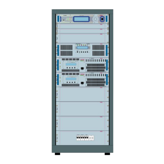
2 PTX100DDS exciter 1 SCML1+1SL/V2 changeover 1 HC2-5GRL hybrid coupler 2 PJ2500LCD amplifier The standard configuration of the TX05KSS/61D082B foresees one 19” 27HE rack (see figure below). The manufacturer will produce upon customers request special configurations. ELETTRONIC... - Page 10 ELETTRONIC ELETTRONIC ELETTRONICA Note: This manual gives system-level information about the TX05KSS/61D082B and TX05KSS/61S082. Further details about the operation of the single components please refer to the relative manuals, that are attached to the present one and should be considered a part of it.
-
Page 11: Installation And Use
To install both the TX05KSS/61D082B and the TX05KSS/61S082 transmitter please refer to the relative technical dossier, particularily about: • Mains supply connection •... - Page 12 TX05KSS/61D082B & TX05KSS/61S082 In this case, provide adequate ventilation of the room. COLD 50cm In alternative is cooled by forced ventilation and the air outlet is located on the roof of machine. Is recommended a length of tube approximetively of 1,5 meter.
- Page 13 TX05KSS/61D082B & TX05KSS/61S082 Connect the overall power cord of machine. The cable can be slid through the cable gland located on the back, or on the roof, of the machine and conductors must be attached to the general disconnecting switch terminals.
- Page 14 TX05KSS/61D082B & TX05KSS/61S082 The following table shows the recommended cable cross-sections: THREE-PHASE SINGLE-PHASE CONNECTOR CABLE SECTION CABLE SECTION Ø Ø Ø Ø Ø Ø Ø Ø Tipically the distribution board contains the thermal-magnetic circuit breakers for each amplifier included in the system and one for service.
-
Page 15: First Start
TX05KSS/61D082B & TX05KSS/61S082 LEFT LEFT EXCITER 1 RIGHT RIGHT ÷ AES-EBU / OPTICAL AES-EBU / OPTICAL LEFT EXCITER 1 RIGHT AES/EBU - OPTICAL Audio connections of a system in double exciter configuration Note: In dual exciter configuration is necessary to insert an audio splitter (not included by default). - Page 16 TX05KSS/61D082B & TX05KSS/61S082 WARNING The following information is needed in order to perform the change of output power. The non-respect of this content may cause damage to the equipment or to the people. Menus and images are for illustration purposes only and may differ from rea- lity.
- Page 17 TX05KSS/61D082B & TX05KSS/61S082 Note: during the RF output power rising, check the reflected power level (on amplifier) to verify the antenna status. The transmitter is now up and running at its nominal power level. It is then possible to perform all the controls and verification that one thinks are necessary before putting it into operation.
- Page 18 TX05KSS/61D082B & TX05KSS/61S082 LINE OUT FUSE CPU BACKUP (MAX 6,3A) SUPPLY MAINS FUSE (MAX 6,3A) MAINS VOLTAGE RED=RS485 10MHz REMOTE Digital OUT R.F. OUTPUT RS232 GREEN=RS232 50 Ω SCA1 SCA2 MPX UNBAL Monitor 19KHz Pilot 1PPS RDS Remote R.F. TEST...
- Page 19 TX05KSS/61D082B & TX05KSS/61S082 CPU BACKUP LINE OUT FUSE (MAX 6,3A) SUPPLY MAINS FUSE (MAX 6,3A) MAINS VOLTAGE RED=RS485 10MHz REMOTE Digital OUT R.F. OUTPUT RS232 GREEN=RS232 50 Ω SCA1 SCA2 MPX UNBAL Monitor 19KHz Pilot 1PPS RDS Remote R.F. TEST...
- Page 20 TX05KSS/61D082B & TX05KSS/61S082 5.2.4 Connections of a system in single exciter configuration EXCITER HYBRID COUPLER FWD PWR RFL PWR ÷ AMPLIFIER 1 AMPLIFIER 2 Single exciter configuration User Manual / 20 Rev. 1.0 - 28/10/16...
- Page 21 TX05KSS/61D082B & TX05KSS/61S082 CPU BACKUP LINE OUT FUSE (MAX 6,3A) SUPPLY MAINS FUSE (MAX 6,3A) MAINS VOLTAGE RED=RS485 10MHz REMOTE Digital OUT R.F. OUTPUT RS232 GREEN=RS232 50 Ω SCA1 SCA2 MPX UNBAL Monitor 19KHz Pilot 1PPS RDS Remote R.F. TEST...
- Page 22 TX05KSS/61D082B & TX05KSS/61S082 CPU BACKUP LINE OUT FUSE (MAX 6,3A) SUPPLY MAINS FUSE (MAX 6,3A) MAINS VOLTAGE RED=RS485 10MHz REMOTE Digital OUT R.F. OUTPUT RS232 GREEN=RS232 50 Ω SCA1 SCA2 MPX UNBAL Monitor 19KHz Pilot 1PPS RDS Remote R.F. TEST...
-
Page 23: First Operations
TX05KSS/61D082B & TX05KSS/61S082 6. Base Operations 6.1 Exciter (PTX DDS) (PTX DDS) • Set the exciters following the instructions of the exciters that you are used to set the desired operating frequency. Adjust the output power of exciter to the power required to drive your transmitter. - Page 24 TX05KSS/61D082B & TX05KSS/61S082 |Freq. :000.000Mhz| |F.Step:000 kHz| |P.Out :000 |Rise t:000 Sec| |FWD |RFL |Admin---[Exit]---| Select the FREQ field (working frequency), rotate the encoder and then press it to enter in modality of parameter modification. Adjust the frequency by turning the encoder. Note that when you press the encoder to store the new frequency, the software requires confirmation about this value (“Are you sure?”).
-
Page 25: Amplifier (Pj Lcd)
TX05KSS/61D082B & TX05KSS/61S082 |Input :Analog |Mode A:Mono |Mode D:Auto |Mode X:Stereo |Preemp: uS | |PilLev:+00.0 dB | |PilPhs:+00.0 Deg| |Admin---[Exit]---| Select the Input (audio input modality or the automatic rescuer activation. The status can be set Analog (analogic inputs), Digital (digital inputs), MPX (composite input) -
Page 26: Changeover (Scml1+1Sl)
TX05KSS/61D082B & TX05KSS/61S082 6.3 Changeover (SCML1+1SL) • Set the changeover between exciters following the instructions below. Before that you enable the delivered power from main exciter, it is suggested to check and, in case, correct the basic parameters under own necessity: •... - Page 27 ______________________________________________________________________________ ______________________________________________________________________________ ______________________________________________________________________________ ______________________________________________________________________________ ______________________________________________________________________________ ______________________________________________________________________________ ______________________________________________________________________________ ______________________________________________________________________________ ______________________________________________________________________________ ______________________________________________________________________________ ______________________________________________________________________________ ______________________________________________________________________________ ______________________________________________________________________________ ______________________________________________________________________________ ______________________________________________________________________________ ______________________________________________________________________________ ______________________________________________________________________________ ______________________________________________________________________________ ______________________________________________________________________________ ______________________________________________________________________________ ______________________________________________________________________________ ______________________________________________________________________________ ______________________________________________________________________________ ______________________________________________________________________________ ______________________________________________________________________________...
- Page 28 ISO 9001:2000 certified since 2000 R.V.R Elettronica S.p.A. Via del Fonditore, 2 / 2c Zona Industriale Roveri · 40138 Bologna · Italy Phone: +39 051 6010506 · Fax: +39 051 6011104 e-mail: info@rvr.it ·web: http://www.rvr.it The RVR Logo, and others referenced RVR products and services are trademarks of RVR Elettronica S.p.A. in Italy, other countries or both. RVR ® 1998 all rights reserved. All other trademarks, trade names or logos used are property of their respective owners.
Need help?
Do you have a question about the TX05KSS/61D082B and is the answer not in the manual?
Questions and answers