Table of Contents
Advertisement
Quick Links
Advertisement
Table of Contents

Subscribe to Our Youtube Channel
Related Manuals for R.V.R. Elettronica PTX-DDS


Summary of Contents for R.V.R. Elettronica PTX-DDS
- Page 1 PTX-DDS User Manual Manufactured by Italy...
- Page 2 J. H. Berti 29/11/2010 Major Upgrade J. H. Berti 24/11/2011 External dip-switch upgrade J. H. Berti PTX-DDS - User Manual Versione 1.2 © Copyright 2006-2011 R.V.R. Elettronica SpA Via del Fonditore 2/2c - 40138 - Bologna (Italia) Phone: +39 051 6010506...
-
Page 3: Table Of Contents
PTX-DDS Table of Contents Preliminary Instructions Warranty First Aid Treatment of electrical shocks Treatment of electrical Burns General Description Quick guide for installation and use Preparation First power-on and setup External Description Front Panel Rear Panel Connector Descriprion Operating System... - Page 4 PTX-DDS This page was intentionally left blank Rev. 1.2 - 24/01/11 User Manual...
-
Page 5: Preliminary Instructions
If it is decided to return the that the manufacturer’s instructions are been followed. unit to the factory, R.V.R. Elettronica will mail you a regular authorization with all the necessary instructions to send back the goods;... -
Page 6: First Aid
• Do not interrupt the rythm of compressions when the second person is giving breath. R.V.R. Elettronica SpA Via del Fonditore, 2/2c • Call for medical assistance as soon as 40138 BOLOGNA ITALY possible. -
Page 7: General Description
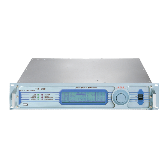
PTX-DDS 4. General Description The PTX-DDS is a FM digital exciter, DDS (Direct Digital Synthesizer), featuring a 19” RACK-mountable form factor. User interface consists of a graphic liquid crystal display and a knob (encoder). This interface lets you view all parameters relating to machine operation and adjust settable parameters (e.g.: power level or working frequency). -
Page 8: Quick Guide For Installation And Use
PTX-DDS Quick guide for installation and use This section provides a step-by-step description of the machine installation and configuration procedure. Follow these procedures closely upon first power-on and each time any change is made to general configuration, such as when a new transmission station is added or the amplifier is replaced. Once the desired configuration has been set up, no more settings are required for normal operation; at each power-up (even after an accidental shutdown), the amplifier defaults to the parameters set during the initial configuration procedure. - Page 9 Elettronica) to the RF output (see figure 6.2 - item [3]) using a 50-Ohm coaxial cable with “N”-type connectors. Note: When you connect the PTX-DDS to other devices, it is necessary to strictly follow the instructions given by the resepective manufacturers, to avoid damages or danger situations. WARNING: Electric shock hazard. Never handle the RF output connector when the machine is powered on and no load is connected.
-
Page 10: First Power-On And Setup
The equipment doesn’t work correctly? Answer: • Ensure that the LOCK light turns on (see figure 6.1 - item [1]). It indicates the PLL is locked to working frequency, wait at least 15 seconds from the power on of PTX-DDS. 5.2.3 Power check Question: The equipment doesn’t work correctly at the power set up? Answer: •... - Page 11 PTX-DDS • Check current RF output setting and enable output (if not already enabled) following menu path Admin ⇒ RfSet ⇒ Pwr ⇒ ON (chap. 7.4.3.1). Otherwise is possible enable the output power directly from main menu (chap. 7.4.1). Output power can also be set in a Pwr OFF condition; in this condition, (Fwd) output power reading on the display will be 0 (zero), that will be delivered the moment you switch back to Pwr ON state.
- Page 12 PTX-DDS Dip-Switch Set ON Set OFF C Bus disconnected. C Bus connected. 1 (SW1) - Analogic Input 5 activated. - Analogic Input 5 deactivated. - Analogic Input 6 activated. - Analogic Input 6 deactivated. 2 (SW1) Not used Not used...
- Page 13 PTX-DDS 5.2.8 Changing the external dip-switch configuration To change the external dip-switch configuration; switch off the equipment (if it power on) and disconnect the mains power cable, then unscrewing all the screws present. Remove the equipment from the rack and identify the bottom panel (see figure below); configurate the dip-switch referred to the own necessity. Figure 5.2 Dip-Switch ON position OFF position 1 & 2 L&R Input Impedance...
-
Page 14: External Description
PTX-DDS 6 External Description This section describes the components found on the front and rear panel of PTX- DDS. 6.1 Front Panel Figure 6.1 [1] LOCK Green LED, it is lit on when the PLL is locked to working frequency. [2] ON Green LED, it is lit on when the exciter is switched on. [3] ALARM Red LED, it is lit on in presence of transmitter failure in case of hardware alarms (for example communicaton lack between the modules). In case the LED flashing, it indicates the temperature alarm. -
Page 15: Rear Panel
PTX-DDS 6.2 Rear Panel Figure 6.2 [1] PLUG Mains power plug and Mains power switch. [2] FAN Forced cooling fan. [3] RF Output RF output connector, N-type, 50Ω. [4] Remote DB15 connector for telemetry of the machine. [5] SLOT Slot allocation for the options. [6] SCA1 BNC input connector, SCA1 unbalanced. [7] DIGITAL OUT Not available (reserved for future uses). [8] SCA2 BNC input connector, SCA2 unbalanced. [9] DIGITAL OUT Not available (reserved for future uses). [10] MPX UNBAL BNC input connector, MPX unbalanced. [11] MONITOR BNC output connector for internal MPX signal monitoring. [12] 19 kHz pilot BNC output connector for output tone control, may be used to synchronise external devices (such as RDS coder). -
Page 16: Connector Descriprion
PTX-DDS 6.3 Rear Panel 6.3.1 Remote Type: Female DB15 Ext Rem Interlock input, disables tx if connected to ground Ext Fwd Pwr Analogue input for forward power from external amplifier Analogue Input 5 (0 - 5V) or I C bus SDA (*) -
Page 17: Operating System
PTX-DDS 7. Operating System The exciter is controlled by a microprocessor system. Software operations may be grouped into two broad categories: start-up and normal operation. 7.1 Using the encoder The interaction between the user and the exciter’s control software is performed using the encoder. -
Page 18: Start-Up
Figure 7.3 After approximately 10 seconds this screen is replaced with the default screen (see chap. 7.4.1). 7.3 Operating System The PTX-DDS menu system consists of a default menu and set of administration menus. The logic of the organization of the display is represented in the figures belows. 14 / 54 Rev. 1.2 - 24/01/11... - Page 19 PTX-DDS Space for Space for graphic informations: symbols of Menu default 7 characters for info background 8 characters for operations measurement |---------[Admin]-[Maint]- 3 characters for unit of measurement |Menu1| |Menu2| VMeter |Menu3| |Menu4| Applications bar |Menu5| |Menu6| |Menu7| |-------Exit--------|Exit | Figure 7.4...
-
Page 20: Menu Organization
PTX-DDS 7.4 Menu Organization 7.4.1 Default menu (MAIN) This is an information screen; it shows the main amplifier measures, most of this cannot be modified. Only RF Status, Frequency and Power Output are quickly modifiable from this menu. If the illumination of the display is turned off, the first pressure or rotation of the encoder cause the lighting. To change the editable parameters press the encoder, turn until the indicator is highlighted on the desired menu and then press again to confirm. The setting of the value is now possible by the rotating of the encoder. - Page 21 PTX-DDS 7.4.2 Maintenance menu Maint Under this menu are available detailed information regarding the status of the equipment, most of these cannot be modified but are only visualized. Turning the encoder, you can move the cursor to the next submenu label, while its informations and measures appears in the centre of the window.
- Page 22 PTX-DDS PAmea 7.4.2.2 Power amplifier measures submenu ( This menu provides general information on the power amplifier measures. |VPA : 00.0 |IPA : 00.0 |VCO : 00.0 |Temp. : + 00 °C | |ExtFWD:000.0 |ExtRFL:000.0 |Maint------------| Figure 7.7 Visualization of the feeding voltage of power amplifier expressed in Volt. Visualization of the absorbed current of power amplifier expressed in Ampere. Visualization of the voltage applied to VCO section expressed in Volt.
- Page 23 PTX-DDS AuLev 7.4.2.3 Audio level submenu ( This menu provides general information on the input audio level measures of the exciter. |Ana. R:+00.0 dBr| |Ana. L:+00.0 dBr| |Dig. R:+00.0 dBr| |Dig. L:+00.0 dBr| |MX/SCA:+00.0 dBr| |Maint------------| Figure 7.8 Ana. R Visualization of the right analogic channel level expressed in decibel (dBr).
- Page 24 PTX-DDS AuCnt 7.4.2.4 Audio control submenu ( This menu provides general information on the audio control measures of the exciter. |Clip. :OFF |ClipLR:+00.0 dB | |Clip X:+00.0 dB | |Ph.Ana:+(L = R) |Ph.Dig:+(L =-R) |PhsMpx:-( MPX ) |Maint------------| Figure 7.9...
- Page 25 PTX-DDS BdCnt 7.4.2.5 Board control submenu ( This menu provides general information on the exciter control adjustments of the exciter. |Input :Analog |Mode A:Mono |Mode D:Auto |Mode X:Stereo |Preemp: uS | |PilLev:+00.0 dB | |PilPhs:+00.0 Deg| |Maint------------| Figure 7.10 Input Visualization of the audio input modality or the automatic rescuer activation.
- Page 26 PTX-DDS OuLev 7.4.2.6 Output level submenu ( This menu provides general information on the output level measures. |Dig. R:+00.0 dBf| |Dig. L:+00.0 dBf| |Monit.:+00.0 dBu| |Pilot :+00.0 dBu| |Maint------------| Figure 7.11 Dig. R Visualization of the ouput level for the right digital channel expressed in decibel (dBfs).
- Page 27 PTX-DDS ITUst 7.4.2.7 I.T.U. and A.G.C status Submenu ( This menu provides general information on the ITU (International Telecommunications Union) and AGC (Automatic Gain Control) setups. |ITU |ITULev:+00.0 dB | |ITUadj:+00.0 dBr| |AGC :OFF L&R| |AGC LR:+00.0 dB | |AGC...
- Page 28 PTX-DDS RDSst 7.4.2.8 RDS status submenu ( This menu provides general information on the RDS (Radio Data System) setups. |DSN |PTY |Maint------------| Figure 7.13 Visualization of the DSN put on the air (Data Source Name). Visualization of the text put on the air (Program Service).
- Page 29 PTX-DDS EXTst 7.4.2.9 External status submenu ( This menu provides general information on the external analogic status. 0.00 0.00 0.00 0.00 : Disabled | : Disabled | |MAINS : Disabled | |Maint------------| Figure 7.14 Visualization of the input voltage on pin 6 of REMOTE connector expressed in Volts (max 5 V).
- Page 30 PTX-DDS AlmLt 7.4.2.10 Alarms list submenu ( This menu provides general information on the last twenty alarms stored in a non volatile memory from the exciter. In case the buffer is full, the previous alarms stored will have replaced with the new one, normally it visualized the last alarm saved in memory.
- Page 31 PTX-DDS Info 7.4.2.11 Firmware informations submenu ( This menu provides general information on the firmware installated and jumper setting in the exciter. Note: if the version isn’t supported is displayed “!!!ERROR!!!” (i.e.: after a new release firmware upgrade). |Bios:BIOS-000300 | |App.:PTDS-000100 | |Pan.:PDDS-000100 | |Aud.:TRDP-000100 | |Tab :PDDS-0150-01| |Jumper: |12345678 12345678| |Maint------------| Figure 7.16...
- Page 32 PTX-DDS InfoM 7.4.2.12 Modem informations submenu ( This menu provides general information on the modem in case it is installated. |SCN:+393359609600| |Nam:I TIM |SigLev:-99 |Retry : |Dial :ATDT |N. SMS: 50 |Stat.:Not in use | |Maint------------| Figure 7.17 Visualization of the Service Centre Number.
- Page 33 PTX-DDS 7.4.3 Administration menu Admin Under this menu are available advanced information regarding the status of the equipment and most of these can be modified. Turning the encoder, you can move the cursor to the next submenu label, while its informations and measures appears in the centre of the window.
- Page 34 PTX-DDS RFset 7.4.3.1 RF setting submenu ( This menu provides general the RF setting of the exciter. |Freq. :000.000Mhz| |F.Step:000 kHz| |P.Out :000 |Rise t:000 Sec| |FWD |RFL |Admin---[Exit]---| Figure 7.18 Selection of the equipment power status. The status can be set ON (RF power output enabled) or OFF (RF power output disabled).
- Page 35 Selection of the threshold level for “forward power good” signal. Level is expressed as percentage of set power level. The activation of power good is on when PTX-DDS actual output power exceeds this percentage of nominal power. For example: assuming that power set in the default menu is 70% of machine rated power (i.e.: PTX100DDS 70% x 100W = 70W) and PG1 is set to 80%...
- Page 36 PTX-DDS AuREG 7.4.3.3 Audio regulation submenu ( This menu provides the audio level setting of the exciter. When the exciter is set in STEREO mode from the BdSet menu (see chap. 7.4.3.5), the same level adjustment is forced on both channels.
- Page 37 PTX-DDS AuSet 7.4.3.4 Audio setting submenu ( This menu provides the audio control setting of the exciter. |Clip. :OFF |ClipLR:+00.0 dB | |Clip X:+00.0 dB | |Ph.Ana:(L = R)+ |Ph.Dig:(L =-R)+ |Ph.Mpx:( MPX )- |Admin---[Exit]---| Figure 7.21 Clip Selection of the clipper modality. The status can be set OFF (Clipper...
- Page 38 PTX-DDS BdSet 7.4.3.5 Board setting submenu ( This menu provides the exciter control setting. In case of passage from Mono to Stereo modality, the left channel adjusments are replicated on the right channel. |Input :Analog |Mode A:Mono |Mode D:Auto |Mode X:Stereo...
- Page 39 PTX-DDS OuReg 7.4.3.6 Output regulation submenu ( This menu provides the output level setting of the exciter. |Dig. R:+00.0 dBf| |Dig. L:+00.0 dBf| |Monit.:+00.0 dBu| |Pilot :+00.0 dBu| |Admin---[Exit]---| Figure 7.23 Dig. R Selection of the ouput level for the right digital channel expressed in decibel.
- Page 40 PTX-DDS 7.4.3.7 I.T.U. and A.G.C setting Submenu ( This menu provides the ITU (International Telecommunications Union) and AGC (Automatic Gain Control) setting of the exciter. |ITU |ITULev:+00.0 dB | |ITUadj:+00.0 dBr| |AGC :OFF L&R| |AGC LR:+00.0 dB | |AGC :OFF...
- Page 41 PTX-DDS 7.4.3.8 RDS setting submenu ( The menu provides the RDS (Radio Data System) setting of the exciter. The enabling for RDS operation is dependent also from the selection into the BdSet menu (chap. 7.4.3.5). |RDS |Level : mV | |Phase : °...
- Page 42 PTX-DDS 7.4.3.9 SFN submenu ( This menu provides the SFN (Single Frequency Network) setting of the exciter. |P.Red.:ON |PpsInt:100 min| |PpsRec: 10 min| |GpsInt:200 min| |GpsRec: min| |Power : 50 |Delay : 0.000 us| |Admin---[Exit]---| Figure 7.26 Enable Selection of the SFN modality in case of synchrony lack.
- Page 43 PTX-DDS 7.4.3.10 FSK submenu ( This menu provides the FSK (Frequency Shift Keying) setting of the exciter. |Enable:OFF |Offset: 10 kHz| |ReTime: 10 min| |Code :RVRCOD |Admin---[Exit]---| Figure 7.27 Enable Selection of the FSK modality. The status can be displayed ON (FSK function enabled) or OFF (FSK function disabled).
- Page 44 PTX-DDS AlSet 7.4.3.11 Alarms setting submenu ( This menu provides the alarm setting of the exciter. |FWD :00% 000s| |RFL :00% 000s| |Audio :00kHz 000s| |Mains : 000s| |ExtFWD:00% 000s| |ExtRFL:00% 000s| |Admin---[Exit]---| Figure 7.28 Selection of the alarm activation level in case of forward power lack expressed in percentage.
- Page 45 PTX-DDS Aresc 7.4.3.12 Alarms rescuer submenu ( This menu provides the alarm rescuer of the exciter. For more information about this menu, please read chapter 7.6. |Status:Disable |AnaLev:-00 dBr| |DigLev:-00 dBr| |MpxLev:-00 dBr| |PilLev:-00 dBr| |CngTmr:000s 000s | |RecTmr:000m 000m | |Admin---[Exit]---| Figure 7.29...
- Page 46 PTX-DDS GnSet 7.4.3.13 General setting submenu ( This menu provides the general setting (as modem, serial interface, time, etc.) of the exciter. |Uart |Baud : 9600 |Modem :Absent |Lang. :English |Date :00/00/00 |Time :00:00:00 |Admin---[Exit]---| Figure 7.30 Uart Selection of the address for I C and serial communications, selectable from 1 to 200.
-
Page 47: Set Up Reset
PTX-DDS 7.5 Set up Reset To reset completely the PTX-DDS to the factory set up, if necessary, follow the next instructions. The user must hold pressed the encoder, therefore switch on the PTX-DDS, it will be displayed the following screen:... -
Page 48: Audio Rescuer
PTX-DDS 7.6 Audio Rescuer 7.6.1 Preliminary Considerations The TRDSP card has available an Optical-AES/EBU digital input, two balanced analog inputs (audio channel left and right) for stereo broadcast, unbalanced MPX input scanned up to 100 kHz and 2 SCA adjustable inputs mixed in analogic with MPX input. - Page 49 PTX-DDS Analogic Digital Audio MPX Audio Digital Pilot Tone Audio level Level Level Stream Plot STEREO R & L - - - - - - - - - - - - - - - - Analogic MONO L - - - -...
- Page 50 PTX-DDS 7.6.4 Operation of rescuer First of all, select the audio input modality or the automatic rescuer activation BdSet through Board setting submenu ( State 1 State 2 State 3 Mode 1 A (analogic) Mode 2 D (digital) Mode 3...
-
Page 51: I.t.u
PTX-DDS 7.7 I.T.U. The I.T.U. function is active only when the internal coder works, it has been implemented to monitor the output of complete MPX process. When you enable this function, the AGC is automatically switched off and the CLIPPER R & L function is added. - Page 52 PTX-DDS 7.8.2 A.G.C. function for MPX channel The A.G.C. of MPX input works in identical mode to audio input but with a value range up to 6dB. This control alters the level of SCA inputs of the same amount needed to correct the signal present on MPX.
-
Page 53: Technical Specification
PTX-DDS 8. Technical Specification PTX30-DDS U.M. Parameters Conditions GENERALS Frequency range 87.5 ÷ 108 Frequency programmability From software, with 1 kHz steps Rated output power Modulation type Direct Digital Synthesis Operational Mode Mono, Stereo, Multiplex 0 to + 50 (operational -10) Ambient working temperature °C... - Page 54 PTX-DDS PTX100-DDS PTX150-DDS Notes 87.5 ÷ 108 87.5 ÷ 108 From software, with 1 kHz steps From software, with 1 kHz steps Continuously variable by software from 0 to maximum Direct Digital Synthesis Direct Digital Synthesis Mono, Stereo, Multiplex Mono, Stereo, Multiplex...
-
Page 55: Modules Identification
PTX-DDS 9. Modules Identification The PTX-DDS is made up of various modules linked to each other through connectors so as to make maintenance and any required module replacement easier. 9.1 Top View The figure below shows the equipment top view with the various component pointed out Figure 9.1... -
Page 56: Power Supply Unit
PTX-DDS 9.2 Power supply unit The PTX-DDS power supply unit is a switching-type unit whose +34 V main output powers the machine’s RF amplifier. The power supply also features stabilizers for generating continuous +5 V, -15V, +8V and +18 V voltages for powering the other device circuits. 9.3 Power amplifier The power amplifier is available in a 30W,100W and 150W version. The final power stage is enclosed in a fully shielded metal container fixed to the central part of the device. -
Page 57: 16-Bit Cpu Card
The 1Mb Flash Memory enables firmware update through direct connection of PTX-DDS RS232 output to the serial port of a PC. Card specifications are as follows: • Microprocessor: 90F5436 •... - Page 58 At TRDSP output, the total signal (MPX + RDS) is converted into analogue form (D/A) and passed on to the standard up-converter section of PTX-DDS. 54 / 54 Rev. 1.2 - 24/01/11...
Need help?
Do you have a question about the PTX-DDS and is the answer not in the manual?
Questions and answers