Table of Contents
Advertisement
Quick Links
Advertisement
Table of Contents

Subscribe to Our Youtube Channel
Related Manuals for Raisecom ISCOM2924GF


Summary of Contents for Raisecom ISCOM2924GF
- Page 1 ISCOM2924GF Hardware Installation User Manual...
- Page 2 Raisecom Technology Co., Ltd shall not be held liable for errors contained herein or direct, indirect, special, incidental or consequential damages in connection with the furnishing, performance, or use of this material.
- Page 3 Tel: +86-10-82883305 Fax: +86-10-82883056 World Wide Web You can access the most current Raisecom product information on the World Wide Web at the following URL: http://www.raisecom.com Feedback Comments and questions about how the ISCOM2924GF device works are welcomed. Please review...
-
Page 4: Table Of Contents
CONTENTS Chapter 1 Overview ------------------------------------------------------------------------------------- 1 1.1 Overview of this manual---------------------------------------------------------------------------------------------------3 1.2 Terms explanation-----------------------------------------------------------------------------------------------------------3 Chapter 2 Specification and Dimension ---------------------------------------------------------- 4 2.1 Device hardware description --------------------------------------------------------------------------------------------4 2.2 Device dimension------------------------------------------------------------------------------------------------------------4 2.3 Device operating environment ------------------------------------------------------------------------------------------4 Chapter 3 Device Appearance ----------------------------------------------------------------------- 5 3.1 Device front panel description ------------------------------------------------------------------------------------------5 3.2 Device rear panel description -------------------------------------------------------------------------------------------6 Chapter 4... - Page 5 Preface About This Manual This manual is for users of ISCOM2924GF switch with hardware version higher than VER. A.00. Who Should Read This Manual This manual is a reference for device installation and maintenance staff. Relevant Manuals 《ISCOM2924GF Series Switches Commands Notebook》...
- Page 6 User Manual General Safety Instructions The following instructions serve as a general guide for the safe installation and operation of telecommunications products. Additional instructions, if applicable, are included inside the manual. Safety Symbols This symbol may appear on the equipment or in the text. It indicates potential safety hazards regarding product operation or maintenance to operator or service personnel.
- Page 7 User Manual be present inside certain products even when the power switch (if installed) is in the OFF position or a fuse is blown. For DC-powered products, although the voltages levels are usually not hazardous, energy hazards may still exist.
-
Page 8: Chapter 1 Overview
Chapter 1 Overview 1.1 Overview of this manual This manual mainly discusses the installation of ISCOM2924GF switch. It describes the features of the switch, introduces its components and the functions these components accomplish. The manual brings forth a normative installation procedure for users and explains the types and specifications of all cables applied during the installation. -
Page 9: Chapter 2 Specification And Dimension
Chapter 2 Specification and Dimension 2.1 Device hardware description ISCOM2924GF Ethernet Switch is a layer-2 Ethernet switch designed for network users’ access to the carriers’ network. ISCOM2924GF provides 20 1000BASE-X Ethernet interfaces in the form of SFP and 4 combo interfaces (in support of both 1000BASE-X in the form of SFP and 10/100/1000BASE-T in the form of RJ-45). -
Page 10: Chapter 3 Device Appearance
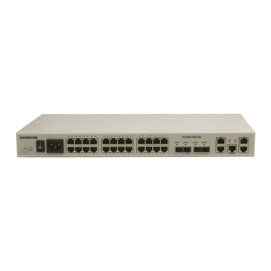
ISCOM2924GF switch (see the figure below). In the figure shown above: ① The logo and model of the switch are RAISECOM and ISCOM2924GF respectively. ② 3 device status indicators: SYS, PWR1 and PWR2. Indicator... -
Page 11: Device Rear Panel Description
⑥ The CONSOLE interface. 3.2 Device rear panel description ISCOM2924GF’s rear panel is shown in the figure below. In the figure shown above: ① Socket for power supply (Can be socket for 220V AC power supply or -48V DC power supply... - Page 12 User Manual according to the configuration.) ② Switch for the power supply ③ Device grounding terminal...
-
Page 13: Chapter 4 Installation And Application
4.2 Device installation 4.2.1 Environment requirement There are heat exhaust outlets on both sides of ISCOM2924GF switch. Please leave space on both sides of the switch to keep air flow unblocked. Please make sure the outlets are not blocked. 4.2.2 Install the device on to a rack To set the switch firmly into a rack, please fix the installation tray to the switch using the eleven screws come with the device and fasten the installation handle on to the rack. - Page 14 The pin number and pin function definition of 9-pin serial port connector is shown in the figure and table below. Function Type Function Type Number Number 3) CONSOLE interface connecting pattern and parameter setup The connecting of ISCOM2924GF CONSOLE interface and PC serial port is shown in the figure below.
-
Page 15: Connect To Ethernet
The auto-adaptation function of all the interfaces is enabled by default. The 4 Ethernet electrical interfaces in the 4 combo interfaces of ISCOM2924GF switch have Auto MDI/MDIX function. The interface can switch between MDI and MDIX automatically. The connection can be established successfully regardless of the type of interface (MDI or MDIX) the opposite site of the connection adopts or the type of cable (straight through or crossover) applied. -
Page 16: Connect To The Power Supply
PC with MDI interface by straight through cable. 4.3.3 Connect to the power supply ISCOM2924GF-AC adopts 220V AC power supply. Please connect the socket on the rear panel of the switch with 220V AC power supply using the provided power supply cable. -
Page 17: Electrify The Switch
User Manual Side 1 Side 1 Side 2 3 5 7 1 = White/Orange 1 = White/Green 2 = Orange 2 = Green 3 = White/Green 3 = White/Orange 4 = Blue 4 = White/Brown 5 = White/Blue 5 = Brown... -
Page 18: Chapter 5 Notes
User Manual Chapter 5 Notes The installation, maintenance, plugging in and pulling out of components of ISCOM2924GF switch can only be conducted by qualified technical support staff. Please place the device in a temperature-controllable and humidity-controllable room and please be cautious of the conductivity of the materials around the device. - Page 19 Address: 2 Floor, South Building of Rainbow Plaza, No.11 Shangdi Information Road, Haidian District, Beijing Postcode: 100085 Tel: +86-10-82883305 Fax: +86-10-82883056 Email: export@raisecom.com http://www.raisecom.com...
Need help?
Do you have a question about the ISCOM2924GF and is the answer not in the manual?
Questions and answers