Table of Contents
Advertisement
Advertisement
Table of Contents

Related Manuals for Donaldson Torit Downflo II DFT 2-4


Summary of Contents for Donaldson Torit Downflo II DFT 2-4
-
Page 3: Table Of Contents
Downflo II, Models DFT 2-4 and DFT 3-6 Contents Description ............4 Preliminary Start-Up Check ....... 20 Purpose and Intended Use ........4 Optional Equipment ........... 21 Operation ............. 5 5-Gallon Pail Pack ........21 Inspection on Arrival ........... 6 55-Gallon Drum Pack ........ -
Page 4: Description
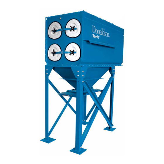
Donaldson Company, Inc. Description The Downflo II dust collector is a continuous-duty ® • For fibrous dust, use a cartridge with an open- collector with cartridge-style filters. The pleat design, such as Fibra-Web ® downward airflow design delivers high filtration •... -
Page 5: Operation
Downflo II, Models DFT 2-4 and DFT 3-6 Operation During normal operation, dust-laden air enters the Filter cleaning is completed using pulse-jet unit through the dirty-air inlet. Airflow is directed technology. A solenoid and diaphragm valve downward through the collector and heavier aligned to each filter provides the pulse cleaning. -
Page 6: Inspection On Arrival
Donaldson Company, Inc. Inspection on Arrival Installation 1. Inspect unit on delivery. Site Selection 2. Report any damage to the delivery carrier. 1. The unit can be located on a reinforced 3. Request a written inspection report from the concrete foundation or rooftop. Claims Inspector to substantiate claim. -
Page 7: Electrical Wiring
Downflo II, Models DFT 2-4 and DFT 3-6 Electrical Wiring Rigging Instructions Caution! Crane or Forklift Pipe Wrenches • Electrical installation must be Slings, Spreader Bars, Socket Wrenches performed by a qualified electrician and Clevis Pins End Wrenches and comply with all applicable Drift Pins Large Crescent Wrench national and local codes. -
Page 8: Standard Equipment
Donaldson Company, Inc. Standard Equipment Standard installation consists of the base unit, leg, 3. Lift the collector and position over the hopper hopper, power pack, electrical, and compressed air and lower slowly. connection. 4. Use drift pins to align holes. Hopper Installation 5. -
Page 9: Leg Installation
Downflo II, Models DFT 2-4 and DFT 3-6 Leg Installation Leg sets are designed for standard height collectors 3. Using a crane, lift the assembled unit onto the and are rated Seismic Zone 4. Reference the anchor bolts. Fasten each leg pad to the anchor drawing shown below and the leg assembly bolts using flat washers, lock washers, and hex drawing shipped with the leg set for proper... -
Page 10: Power Pack Installation
Donaldson Company, Inc. Power Pack Installation Notes: For all top-mounted TBI with and without a Two types of power packs are available for the blast-gate style damper, and top-mounted Downflo II: Torit Backward Incline, TBI, and Torit TRB with a blast-gate style damper, install a Radial Blade, TRB. - Page 11 Downflo II, Models DFT 2-4 and DFT 3-6 Note: For all top-mounted TBI with and 1. The power packs are shipped assembled and without a blast-gate style damper, and partial disassembly is required before installing. top-mounted TRB with a blast-gate style 2.
-
Page 12: Electrical Connection
Donaldson Company, Inc. Electrical Connection 4. Turn the blower motor ON then OFF to check Caution! for proper rotation by referencing the rotation arrow located on the motor’s mounting plate. • Electrical installation must be performed by a qualified electrician and comply with all applicable national and local codes. - Page 13 Downflo II, Models DFT 2-4 and DFT 3-6 The unit is equipped with 115-V solenoid valves Wire the solenoids to the solid-state timer following that control the pulse-cleaning valves, which clean the wiring diagram supplied with the unit. Filter life the filters.
- Page 14 Donaldson Company, Inc. Input Power to the solid-state timer is supplied to Terminals L1 and L2, which operate in parallel 105-135V/50-60Hz/1Ph with the blower starter’s low-voltage coil. On Output Solenoids blower start-up, power is supplied to the timer and the preset OFF time is initiated. At the end of the The load is carried and turned ON and OFF by the OFF time, the timer energizes the corresponding 200 watt maximum-load-per-output solid-state...
-
Page 15: Checker Board Control Panel
Downflo II, Models DFT 2-4 and DFT 3-6 The Checker board provides cleaning control, 2. Make the proper electrical and pneumatic diagnostic review of the operational parameters, connections to the collector and motor starter diagnostic review of the system components, and a following the diagrams and instructions record of operational data and fault conditions for supplied with the Checker board. - Page 16 Donaldson Company, Inc. One of three types of solenoid enclosures, the Input weatherproof NEMA 4 with 1/8-in solenoid valves; Low Range: 90-130V/50-60Hz/1Ph the gas-explosion proof NEMA 7 with 1/8-in High Range: 180-260V/50-60Hz/1Ph solenoid valves; or the dust-explosion proof NEMA Output Relay Voltage and Contact Rating: 9 with 1/8-in solenoid valves, is mounted near or on The output relays are independent of the input the unit’s compressed-air manifold.
- Page 17 Downflo II, Models DFT 2-4 and DFT 3-6 Pulse ON Time Operating Temperature Range Factory set at 100-milliseconds, or 1/10-second. Ambient 0° F to 140° F. Note: Do not adjust pulse ON time unless the Relays proper test equipment is available. Too much or too There are twenty-four relay positions, twenty-three little ON time can cause shortened filter life.
-
Page 18: Compressed Air Installation
Donaldson Company, Inc. Compressed Air Installation 1. Remove the plastic pipe plug from the unit’s air Caution! manifold and connect the compressed-air supply line. Use thread-sealing tape or pipe • The compressed-air supply must be sealant on all compressed-air connections. oil and moisture free. - Page 19 Downflo II, Models DFT 2-4 and DFT 3-6 * customer supplied Compressed Air Installation...
-
Page 20: Preliminary Start-Up Check
Donaldson Company, Inc. Preliminary Start-Up Check 1. Check all electrical connections for tightness To reverse rotation, three-phase power supply: and contact. Turn electrical power OFF at source and switch 2. Check for and remove all loose items in or near any two leads on the output-side of the fan- the inlet and outlet of the unit. -
Page 21: Optional Equipment
Downflo II, Models DFT 2-4 and DFT 3-6 Optional Equipment 5-Gallon Pail Pack 1. Apply sealant to the hopper flange or the pail 2. Fasten the pail pack to the hopper using the cover mounting plate flange toward the inside bolts, washers, and nuts supplied. -
Page 22: 55-Gallon Drum Pack
Donaldson Company, Inc. 55-Gallon Drum Pack The drum pack is designed to fit a customer- 3. Attach the drum cover to the 55-gallon drum. supplied, standard 55-gallon drum and provides 4. Use latches to secure the cover to the drum, if easy access for dust removal and disposal. - Page 23 Downflo II, Models DFT 2-4 and DFT 3-6 4. Use latches to secure the cover to the drum, if 1. Place a 1/4-in diameter, rope-type sealant equipped. between the hopper flange and the adapter as shown. 5. Connect the flexible hose between the drum cover and the adapter.
-
Page 24: Magnehelic Gauge
Donaldson Company, Inc. Magnehelic Gauge The Magnehelic is a differential pressure gauge 5. Plug the pressure ports on the back of the gauge used to measure the pressure difference between using two 1/8-in NPT pipe plugs supplied. the clean- and dirty-air plenums and provides a Install two 1/8-in NPT male adapters supplied visual display of filter change requirements. - Page 25 Downflo II, Models DFT 2-4 and DFT 3-6 Magnehelic Gauge Assembly...
-
Page 27: Photohelic ® Gauge
Downflo II, Models DFT 2-4 and DFT 3-6 4. Thirty-five feet of plastic tubing is supplied and 5. Zero and maintain the gauge as directed in the must be cut in two sections. Connect one manufacturer’s Operating and Maintenance section of tubing from the gauge’s high-pressure Instructions provided. -
Page 28: Delta P Control
Donaldson Company, Inc. Delta P Control When combined with a pulse timer, the Delta P 1. Choose a location near the unit that permits control monitors the differential pressure between access to the keypad for adjustments and the clean- and dirty-air plenums, providing a visual observation of the pressure drop. - Page 29 Downflo II, Models DFT 2-4 and DFT 3-6 setpoint. The auxiliary relay can also be used to tap on the clean-air plenum. Additional tubing activate visual or audible alarms provided by can be ordered from your representative. others. 7. Place the program wire on the solid-state timer 6.
- Page 30 Donaldson Company, Inc. 230-V Power Supply The only user calibration is the zero adjustment of To operate at 230-V, remove two jumpers labeled the display. Due to slight changes in electronic W1 and W3. Reinsert one of the jumpers in position components over time, or pressure differentials within the plant environment, the display may read something other than 0.0 while at rest.
-
Page 31: Damper Installation
Downflo II, Models DFT 2-4 and DFT 3-6 Damper Installation A damper can be added to the power pack outlet to limit and regulate airflow when unit is in operation. 1. Apply sealant around the inside edge of the bolt pattern on the power pack outlet. -
Page 32: Exhaust Grid Installation
Donaldson Company, Inc. Plenum Silencer Exhaust Grid Installation 1. Apply 1/4-in diameter, rope-type sealant 1. Fit the exhaust grid over the radial blade outlet towards the outside edge of the bolt pattern on or the damper assembly, if equipped. the clean-air outlet. 2. -
Page 33: Exhaust Silencer
Downflo II, Models DFT 2-4 and DFT 3-6 Exhaust Silencer Abrasion-Resistant Inlet Collar 1. Remove the unit’s front cover plate. Remove excess sealant from opening. 1. Attach flanges to the power pack outlet using the supplied bolts, washers, and nuts. 2. -
Page 34: Hepa Or Ashrae Afterfilter Installation
Donaldson Company, Inc. HEPA or ASHRAE Afterfilter Installation The afterfilter plenum is mounted on top of the unit 6. Apply sealant to the inside perimeter of the and the blower is positioned inside the plenum. mounting base. Install the plenum to the mounting base using self-threading bolts with 1. -
Page 35: Cold Climate Kit
Downflo II, Models DFT 2-4 and DFT 3-6 Cold Climate Kit A cold climate kit provides heat to the pulse valves 6. Secure junction box to the collector using two to prevent cold weather freeze up. The basic kit, self-drilling screws. for use in applications that have a moderate 7. -
Page 36: Drum Sentry™, Drum-Full Indicator
Donaldson Company, Inc. Drum Sentry™, Drum-Full Indicator The Drum Sentry provides a visual readout of the 4. Place a 1/4-in thick washer on the close nipple 55-gallon drum contents. When the dust level in the and insert in 1 3/8-in diameter hole. drum covers the opening on the bottom of the 5. - Page 37 Downflo II, Models DFT 2-4 and DFT 3-6 9. Trim the 1-in diameter hose to extend into the drum at the desired drum-full level. Note: Dust with low-bulk density such as weld fume require the hose to be immersed a minimum of 6-in.
-
Page 38: Sprinkler Installation
Donaldson Company, Inc. Sprinkler Installation Explosion Vents Caution! Caution! • Personal injury, death, or property Sprinkler systems place a large quantity damage can result from material of water in the dust collector when discharge during venting. activated. Provide adequate drainage to remove water. -
Page 39: Service Information
Downflo II, Models DFT 2-4 and DFT 3-6 Service Information Operational Checklist Note: Place filter part-number label (supplied with 1. Monitor overall performance of the collector. each replacement filter) over the filter part 2. Monitor exhaust. number listed on the unit’s rating plate. 3. -
Page 40: Dust Disposal
Donaldson Company, Inc. Dust Disposal Compressed Air Components 1. Turn unit OFF and empty dust container as Caution! necessary to minimize dust in the hopper. 2. If the optional 55-gallon drum attachment is Turn compressed-air supply OFF and used, empty when drum is 2/3 full. bleed lines before performing service work. -
Page 41: Troubleshooting
Downflo II, Models DFT 2-4 and DFT 3-6 Troubleshooting... - Page 42 Donaldson Company, Inc. Troubleshooting, continued...
- Page 43 Downflo II, Models DFT 2-4 and DFT 3-6...
- Page 44 Donaldson Company, Inc. Troubleshooting, continued g i l . s l i t c s l i g i l i t c l l a . s l i t l l l i e l f...
-
Page 45: Service Notes
Downflo II, Models DFT 2-4 and DFT 3-6 Service Notes i v r... -
Page 48: Warranty
Donaldson warrants to the original purchaser that the major structural components of the goods will be free from defects in materials and workmanship for ten (10) years from the date of shipment, if properly installed, maintained and operated under normal conditions. Donaldson warrants all other Donaldson built components and accessories including Donaldson Airlocks, TBI Fans, TRB Fans, Fume Collector products, Donaldson built electrical control components and Donaldson built Afterfilter housings for twelve (12) months from date of shipment.
Need help?
Do you have a question about the Downflo II DFT 2-4 and is the answer not in the manual?
Questions and answers