
Related Manuals for FREEWAY M205


Summary of Contents for FREEWAY M205
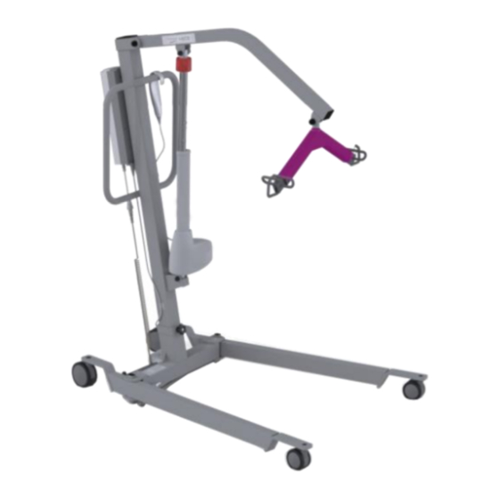
- Page 1 M205 Mobile Hoist Service Manual Doc No. 995069 Revision of document: A Rev Date: 26/04/2021...
-
Page 2: Table Of Contents
Contents 1.0 – Introduction ..................................3 2.0 – Safety Precautions ................................3 3.0 – Annual Servicing ................................4 4.0 – Test Procedure .................................. 5 5.0 – Tools, Equipment and Lubricants Required for Servicing....................6 6.0 – Decommissioning ................................7 7.0 – Spare Parts List .................................. 8 8.0 –... -
Page 3: Introduction
This Manual will explain how to carry out interim servicing and parts replacement on the Freeway M205 Floor Hoist safely and effectively. This document is divided into sections to help a Service Engineer find the correct information. Each section will show in a step by step fashion the correct way to disassemble and assemble the Hoist. -
Page 4: Annual Servicing
3.0 – Servicing To be completed by Approved Service Engineer Maintenance should be completed by an approved service engineer every 6 months to ensure the products required standard is maintained. The service history of the product should be documented each service. When Servicing the Hoist, ensure to fill out the Service Log which is located in the back of the User Manual. -
Page 5: Test Procedure
Verify all Handset functions are in working order. Ensure LED’s are working correctly. Carry Bar: Check that the Carry Bar is able to swivel 360 degrees with ease. This should be done with and without load. Inspect the functionality of the Spring Clips, ensure they return to position once operated, they should be touching the inside of the Carry Bar. -
Page 6: Tools, Equipment And Lubricants Required For Servicing
5.0 – Tools, Equipment and Lubricants Required for Servicing When carrying out work on the Freeway M205 Hoist you will require the following: Tools Required 3mm Allen Key 5mm Allen Key 6mm Allen Key 10mm Spanner 12mm Spanner 13mm Spanner x2... -
Page 7: Decommissioning
6.0 – Decommissioning When the Hoist has completed its life cycle and can no longer perform to its intended use safely the Hoist must be decommissioned by an approved Service Engineer. The following specifies the importance of correct disposal procedure including local laws and being environmentally friendly. Please observe the local laws on recycling and respect the current laws for disposal within the community the device is being used within. -
Page 8: Spare Parts List
510005 Battery Pack (2.9 Ah Lead Acid) 510091 Mains Snap Lead 510092 Charger Lead (UK Plug) 520034 Lift Actuator Lead (700mm) 999069 Freeway M205 User Manual 992069 Freeway M205 Spare Parts Manual 995069 – Revision A Page 8 of 36... -
Page 9: Troubleshooting
For guidance on how to dismantle the hoist to perform troubleshooting actions, see section 9.0 – Servicing. If the fault is not found and/or the solutions do not correct the problem, contact your local Freeway authorized dealer immediately – contact details are provided on the last page of this manual. -
Page 10: Hoist Doesn't Charge
8.2 - Hoist doesn’t charge Connect the Hoist charging lead from the Hoist to the Wall Socket. (Ensuring that the lead is connected properly) to determine if the Hoist charges. If the control box LED does not illuminate a steady orange, follow the Troubleshooting Guide below. Troubleshooting Guide 1. -
Page 11: Hoist Doesn't Lift Load Correctly - Stop/Start Action
Action Guide 1. Remove the Hoist from charge. 2. Connect the Lift Actuator Cable correctly. See section 9.2.2 for guidance. 3. Replace the Cable. See Section 9.2.2 for guidance. 4. Replace the Lift Actuator. See Section 9.5 for guidance. 5. Replace the Control Box. See section 9.3 for guidance 6. -
Page 12: Hoist Leg Actuator Is Not Responding
8.7 - Hoist Leg Actuator is not responding Using the Handset the Hoist Lifting/Lowering function is working but the Powered Leg does not respond to commands. Follow the Troubleshooting Guide below. Troubleshooting Guide 1. Check Cable between the Control Box and the Leg Actuator is connected correctly. 2. -
Page 13: Hoist Doesn't Respond To The Correct Handset Commands
6. Replace the Control Box. See section 9.3 for guidance. 7. See section 9.2.1 for guidance on Handset attachment. Note: Bear in mind this error could be to a specific button on the handset while the other buttons still function. Follow the same procedure. 8.9 –... -
Page 14: Servicing - Removal And Replacement
The step by step process is to be followed in sequence to perform a successful service on the Hoist. Unless stated otherwise, all images refer to a Freeway M205. NOTE: Before carrying out any work on a Freeway M205 Hoist, remember to remove the charger lead and remove any external power source. -
Page 15: Cables
9.2 – Cables In this section it will explain the correct procedure on removing/ refitting the Cables for servicing procedures or replacement. 9.2.1 – Cables - Handset Removal Step 1 – Remove the Handset connecter from the Control Box by pulling downward out of the Port. -
Page 16: Cable - Lift Actuator
9.2.2 – Cable – Lift Actuator Removal Step 1 – Remove the Jack End of the Cable which ports the Control Box by pulling downward. (This is the middle Control Box Port as shown in the image) Step 2 – Release the cable from the Actuator by lifting the locking device upward, it is recommended a flat head screwdriver is used. -
Page 17: Cable - Leg Actuator
Refitting / Replacement Step 5 - Refitting is a reversal of the removal process noting the following points: A) When fitting the Cable into the Actuator port, ensure the locator is facing downward as shown in the image. 9.2.3 – Cable – Leg Actuator Removal Step 1 –... - Page 18 Step 3 – Remove the Cable by pulling it out the port, action may be easier using a flat head screwdriver. Step 4 – Remove the cable from any clips that are routing it along the Hoist. Refitting / Replacement Step 5 - Refitting is a reversal of the removal process noting the following points: A) When fitting the Cable into the Actuator port, ensure the locator aligns correctly for correct connection to the Leg Actuator.
-
Page 19: Cable - Charger
9.2.4 – Cable – Charger Removal Step 1 – Where Applicable, turn the charger off at the wall plug and remove. Step 2 – Detach the Charger lead from the Snap Lead by pulling them apart as shown. Step 3 – Detach the Snap Lead from its latch circled in the image below and pull the lead connecter from the Control Box as arrowed. -
Page 20: Control Box
9.3 – Control Box In this section it will explain the correct procedure on removing and reinstalling the Control Box for servicing procedures or replacement. Removal Step 1 – Remove Battery from the Hoist. (Refer to section 9.1) Step 2 – Remove all the Cabling/leads from the Control Box. (Refer to section 9.2) Step 3 –... -
Page 21: Attachment Bracket
9.4 – Attachment Bracket In this section it will explain the correct procedure on removing and reinstalling the Attachment Bracket for servicing procedures or replacement. Removal Step 1 – Remove the Battery (refer to section 9.1) Step 2 – Remove the Cables/Leads from the Control Box (refer to section 9.2) Step 3 –... -
Page 22: Lift Actuator
9.5 – Lift Actuator In this section it will explain the correct procedure on removing and reinstalling the Lift Actuator for servicing procedures or replacement. Removal Step 1 – Remove the Lift Actuator Cable. (See section 9.2.2) Step 2 - Remove the four Black Caps from the Actuator fixing points. Step 3 –... - Page 23 Step 4 – Pull the Pin out from the top fixing to release the top end of the Actuator. Once this pin has been removed, the boom will need manual support to disallow it from falling. Step 5 – Pull the Pin out from the bottom fixing to release the Actuator, the Actuator can now be removed from the Hoist.
-
Page 24: Leg Actuator
9.6 – Leg Actuator Within this section it will explain the correct procedure on removing and reinstalling the Leg Actuator for servicing procedures or replacement. Removal Step 1 – Remove the Leg Actuator Cable. (Refer to section 9.2.3) Step 2 – Remove the four Black Caps from the Actuator fixing points. Step 3 –... -
Page 25: Carry Bar
9.7 – Carry Bar Within this section it will explain the correct procedure on removing and reinstalling the Carry Bar for servicing procedures or replacement. Removal Step 1 – Remove the two Black Caps from the Carry Bar Pivot. Step 2 – Using two 17mm Spanners, remove a nut and washer from the Carry Bar Pin as shown. -
Page 26: Leg Rod Assembly
Refitting / Replacement Step 4 - Refitting is a reversal of the removal process noting the following point: A) Ensure the Nuts are tight and secure the Carry Bar, do not over tighten as this will bend the framework and will affect the pivoting function of the Carry Bar. B) Apply Loctite 243 to the thread of the Pin. - Page 27 Step 3 – Pull out the spring clip from its positioning within the Leg Rod as shown. Step 4 – Detach the Leg Rod from the Base of the Hoist as shown. Step 5 – Repeat Step two to four to detach the other fixing point of the Leg Rod Assembly to fully detach the Leg Rod.
-
Page 28: Front Castor
9.9 – Front Castor Within this section it will explain the correct procedure on removing and reinstalling the Front Castor for servicing procedures or replacement. Removal Step 1 - Place the Hoist in its side for easier service – Gently rest the Hoist on its side to avoid damage such as paint scratching. -
Page 29: Rear Castor
9.10 – Rear Castor Within this section it will explain the correct procedure on removing and reinstalling the Rear Castor for servicing procedures or replacement. Removal Step 1 - Place the Hoist in its side for easier service – Gently rest the Hoist on its side to avoid damage such as paint scratching. -
Page 30: Leg - (Lh Leg And Rh Leg)
Refitting / Replacement Step 4 - Refitting is a reversal of the removal process noting the following point: A) Ensure that the Castor is secured tightly, there should be no play after fastening. B) Ensure the Castor rotates freely. C) Apply Loctite 243 to the bolt thread. 9.11 –... - Page 31 Step 9 – While pushing the bolt through, remove the TWO washer from the underside of the leg assembly. Step 10 – While pushing the bolt through, remove the THREE washers at the upper face of the Leg assembly. Step 11 – Remove the bolt from the Leg and the leg can be removed. Refitting / Replacement Step 12 - Refitting is a reversal of the removal process noting the following points: A) Ensure the washers are re-inserted into the assembly, with THREE washers on the upper...
-
Page 32: Base
C) Once the Bolt is secured, ensure that the Leg is able to move freely, without any play between the Leg and Base. D) Apply Loctite 243 to the thread on the Bolt. 9.12 – Base Within this section it will explain the correct procedure on removing and reinstalling the Base for servicing procedures or replacement. -
Page 33: Boom
Step 6 - Place the Base Assembly on its side for easier service – Gently rest the Base Assembly on its side to avoid damage such as paint scratching. Step 7 - Remove the Leg Rod Assembly. (Refer to section 9.8) Step 8 –... -
Page 34: Mast
Step 6 – Pull the Pin out of the Boom to release. Step 7 – The Boom can be removed from the Mast. Refitting / Replacement Step 8 - Refitting is a reversal of the removal process noting the following point: A) Ensure when tightening the Boom to the Mast the Boom is able to move freely along with no to little play between the two mating parts. - Page 35 While every effort has been made to ensure the accuracy of information contained in this assembly and installation manual, no liability can be accepted by Freeway for any errors or omissions. Freeway operates a policy of continuous improvement. Specifications and other data are subject to change without notice.
- Page 36 Unit 1• Tir Llwyd Industrial Estate • St Asaph Avenue • Kinmel Bay • Conwy • LL18 5JZ 995069 – Revision A Page 36 of 36...
Need help?
Do you have a question about the M205 and is the answer not in the manual?
Questions and answers