
Related Manuals for FREEWAY SA180C


Summary of Contents for FREEWAY SA180C
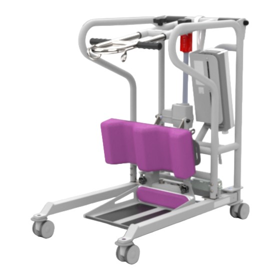
- Page 1 SA180C Stand Aid Service Manual Doc No. 995066 Revision of document: A Rev Date: 26.04.21...
-
Page 2: Table Of Contents
Contents 1.0 – Introduction ......................................3 2.0 – Safety Precautions ....................................3 3.0 – Servicing ........................................4 4.0 – Test Procedure ......................................6 5.0 – Tools, Equipment and Lubricants Required for Servicing ......................... 7 6.0 – Decommissioning ..................................... 8 7.0 – Spare Parts List ......................................8 8.0 –... -
Page 3: Introduction
This Manual will explain how to carry out interim servicing and parts replacement on the Freeway SA180C Stand Aid safely and effectively. This document is divided into sections to help a Service Engineer find the correct information. Each section will show in a step by step fashion the correct way to disassemble and assemble the Hoist. -
Page 4: Servicing
3.0 – Servicing To be completed by Approved Service Engineer Maintenance should be completed by an approved service engineer every 6 months to ensure the products required standard is maintained. The service history of the product should be documented each service. When Servicing the Stand Aid, ensure to fill out the Service Log which is located in the back of the User Manual. - Page 5 Handset and Cables: Inspect the components for damage that may affect the function and safety of the product. Ensure all Cables are fitted to the Control Box correctly. Verify all Handset functions are in working order. Ensure LED’s are working correctly. Upper Assembly: Ensure that the Stainless Steel Assembly is adjustable within the Upper Assembly.
-
Page 6: Test Procedure
4.0 – Test Procedure Below is the full testing procedure required to complete an Annual Stand Aid Service. The SWL (180Kg) is an essential load for the testing of the Stand Aid and a mode of transportation to transport the weights to the hoist is required. 1. -
Page 7: Tools, Equipment And Lubricants Required For Servicing
5.0 – Tools, Equipment and Lubricants Required for Servicing When carrying out work on the Freeway SA180C Stand Aid you will require the following: Tools Required 3mm Allen Key 4mm Allen Key x2 5mm Allen Key x2 6mm Allen Key... -
Page 8: Decommissioning
Leg Actuator Lead (1250mm) 123102 4 Way Handset (Battery & Service LED) 123106 4 Way Control Box (LCD & Data Logging) 119900 Freeway SA180C LH Leg Assembly 119901 Freeway SA180C RH Leg Assembly 119902 Foot Tray Assembly 119903 Rear Castor Assembly... -
Page 9: Troubleshooting
For guidance on how to dismantle the Stand Aid to perform troubleshooting actions, see section 9.0 – Servicing. If the fault is not found and/or the solutions do not correct the problem, contact your local Freeway authorized dealer immediately – contact details are provided on the last page of this manual. -
Page 10: Stand Aid Doesn't Charge
8.2 – Stand Aid doesn’t charge Connect the Stand Aid charging lead from the Stand Aid to the Wall Socket. (Ensuring that the lead is connected properly) to determine if the Stand Aid charges. If the control box LED does not illuminate a steady orange, follow the Troubleshooting Guide below. -
Page 11: Stand Aid Doesn't Lift Load Correctly - Stop/Start Action
Action Guide 1. Remove the Stand Aid from charge. 2. Connect the Lift Actuator Cable correctly. See section 9.2.2 for guidance. 3. Replace the Cable. See Section 9.2.2 for guidance. 4. Replace the Lift Actuator. See Section 9.5 for guidance. 5. -
Page 12: Stand Aid Leg Actuator Is Not Responding
8.7 – Stand Aid Leg Actuator is not responding Using the Handset, the Stand Aid Lifting/Lowering function is working but the Powered Leg does not respond to commands. Follow the Troubleshooting Guide below. Troubleshooting Guide 1. Check Cable between the Control Box and the Leg Actuator is connected correctly. 2. -
Page 13: Stand Aid Doesn't Respond To The Correct Handset Commands
6. Replace the Control Box. See section 9.3 for guidance. 7. See section 9.2.1 for guidance on Handset attachment. Note: Bear in mind this error could be to a specific button on the handset while the other buttons still function. Follow the same procedure. 8.9 –... -
Page 14: Servicing - Removal And Replacement
Stand Aid. The step by step process is to be followed in sequence to perform a successful service on the Stand Aid. Unless stated otherwise, all images refer to a Freeway SA180C Stand Aid. NOTE: Before carrying out any work on a Freeway SA180C Stand Aid, remember to remove the charger lead and remove any external power source. -
Page 15: Cables
Refitting / Replacement Step 3 – Refitting is a reversal of the removal process noting the following points: A) Reposition the Battery above the Control Box – Push the Battery inward and the Battery will “click” into place. 9.2 – Cables In this section it will explain the correct procedure on removing/ refitting the Cables for servicing procedures or replacement. -
Page 16: Cable - Lift Actuator
9.2.2 – Cable – Lift Actuator Removal Step 1 – Remove the Jack End of the Cable which ports the Control Box by pulling downward. (This is the middle Control Box Port as shown in the image) Step 2 – Release the cable from the Actuator by lifting the locking device upward, it is recommended a flat head screwdriver is used. -
Page 17: Cable - Leg Actuator
Step 4 - Remove the cable from any clips that are routing it along the Stand Aid. Refitting / Replacement Step 5 - Refitting is a reversal of the removal process noting the following points: A) When fitting the Cable into the Actuator port, ensure the locator is facing downward as shown in the image. - Page 18 Step 2 – Release the cable from the Actuator by removing the locking device. It is recommended a flat head screwdriver is used. Push the latch outward and push the part downward to remove. Step 3 – Remove the Cable by pulling it out the port, action may be easier using a flat head screwdriver.
-
Page 19: Cable - Charger
9.2.4 – Cable – Charger Removal Step 1 – Where Applicable, turn the charger off at the wall plug and remove. Step 2 – Detach the Charger lead from the snap lead by pulling them apart as shown. Step 3 – Detach the snap Lead from its latch circled in the image below and pull the lead connecter from the Control Box as arrowed. -
Page 20: Control Box
9.3 – Control Box In this section it will explain the correct procedure on removing and reinstalling the Control Box for servicing procedures or replacement. Removal Step 1 – Remove Battery from the Stand Aid. (Refer to section 9.1) Step 2 – Remove all the Cabling/leads from the Control Box. (Refer to section 9.2) Step 3 –... -
Page 21: Attachment Bracket
9.4 – Attachment Bracket In this section it will explain the correct procedure on removing and reinstalling the Attachment Bracket for servicing procedures or replacement. Removal Step 1 – Remove the Battery (refer to section 9.1) Step 2 – Remove the Cables/Leads from the Control Box (refer to section 9.2) Step 3 –... -
Page 22: Lift Actuator
9.5 – Lift Actuator In this section it will explain the correct procedure on removing and reinstalling the Lift Actuator for servicing procedures or replacement. Removal Step 1 – Remove the Lift Actuator Cable. (See section 9.2.2) Step 2 – Using two 4mm Allen Keys, remove one of the screws from the pin at the top Actuator fixing point. - Page 23 Step 5 – Pull the Pin out from the bottom fixing to release the Actuator. Step 6 – Remove the Actuator and rest the Upper Assembly on the Frame as shown. Refitting / Replacement Step 7 - Refitting is a reversal of the removal process noting the following point: A) Ensure the Actuator is fitted in the correct orientation.
-
Page 24: Leg Actuator
9.6 – Leg Actuator Within this section it will explain the correct procedure on removing and reinstalling the Leg Actuator for servicing procedures or replacement. Removal Step 1 – Remove the Leg Actuator Cable. (Refer to section 9.2.3) Step 2 – Using a 6mm Allen Key, remove the two bolts securing the Actuator to the Frame. Step 3 –... -
Page 25: Upper Assembly
9.7 – Upper Assembly Within this section it will explain the correct procedure on removing and reinstalling the Upper Assembly for servicing procedures or replacement. This section includes the full assembly removal as well as the removal of the stainless steel handle. 9.7.1 –... - Page 26 Step 5 – Using a 5mm Spanner, remove the threaded insert which attaches the Upper Handle Assembly to the Frame. Repeat this action to disassemble the other end of the Upper Handle Assembly. Step 6 – Ensure not to lose the washer which is fitted between the two mating parts. Step 7 –...
-
Page 27: Stainless Steel Assembly
D) When fitting the nut, after securing the threaded insert, do not over tighten the nut as this will affect the pivoting function of the Upper Handle Assembly, ensure the Assembly is able to pivot freely without friction. E) Test lowering of the Upper Handle Assembly from the Actuator Maximum height using the handset, if Actuator is not lowering, loosen the nut until lowering is possible. -
Page 28: Leg Rod Assembly
9.8 – Leg Rod Assembly Within this section it will explain the correct procedure on removing and reinstalling the Leg Rod Assembly for servicing procedures or replacement. Removal Step 1 – Place the Stand Aid on its side or front face for easier service – Gently rest it on its side/front to avoid damage such as paint scratching. -
Page 29: Front Castor
Step 7 – To remove the Centre Shaft, remove the nut on the other side using the same spanners. Refitting / Replacement Step 8 - Refitting is a reversal of the removal process noting the following point: A) Ensure that the Centre Shaft is fitted the correct way. B) Ensure both threaded ends are applied with Loctite 243. -
Page 30: Rear Castor
Within this section it will explain the correct procedure on removing and reinstalling the Front Castor for servicing procedures or replacement. Removal Step 1 - Place the Transfer Aid on its side for easier service – Gently rest it on its side to avoid damage such as paint scratching. - Page 31 Within this section it will explain the correct procedure on removing and reinstalling the Rear Castor for servicing procedures or replacement. Removal Step 1 - Place the Stand Aid on its side for easier service – Gently rest it on its side to avoid damage such as paint scratching.
-
Page 32: Leg - (Lh Leg And Rh Leg)
9.11 – Leg – (LH Leg and RH Leg) Within this section it will explain the correct procedure on removing and reinstalling the legs of the Stand Aid, images refer to one leg only but same applies to both. Removal Step 1 –... -
Page 33: Leg Bearing Assembly
9.12 – Leg Bearing Assembly Within this section it will explain the correct procedure on removing and reinstalling the Leg Bearings for servicing procedures or replacement. Images below refer to one side only, but the instructions apply to both bearings on the product. Removal Step 1 - Remove the Leg Actuator Cable. -
Page 34: Foot Tray
9.13 – Foot Tray Within this section it will explain the correct procedure on removing and reinstalling the Foot Tray for servicing procedures or replacement. Removal Step 1 – Remove the Toe Pad by pulling off from the Velcro. (Where applicable) Step 2 –... -
Page 35: Knee Pad
9.14 – Knee Pad Within this section it will explain the correct procedure on removing and reinstalling the Knee Pad for servicing procedures or replacement. Repeat each step for the opposite side of the Knee Pad Assembly as the instructions apply for both. Removal Step 1 –... - Page 36 Step 4 – Remove the Two Caps from the Height Adjustment Plates as shown. Step 5 – Remove the Height Adjustment Plate No.1 by removing the nut and bolt using a 5mm Allen Key and 13mm Spanner. Ensure to grab all washers from the assembly. Step 5 –...
- Page 37 Refitting / Replacement Step 6 - Refitting is a reversal of the removal process noting the following points: A) When reattaching the Height Adjustment Plate No.2, ensure the plate is attached in the correct orientation as shown in step 4. B) When reattaching the Height Adjustment Plate No.2, ensure the washers are all attached in the correct order as shown.
- Page 38 D) When reattaching the Knee Pad Attachment Plate, the correct order is shown in the image below. (Star Handle, Small White Spacer. Knee Pad Attachment Plate, Height Adjustment Plate No.2, Large White Spacer, Height Adjustment Plate No.1 and Clamp Plate) E) When re-attaching the Knee Pad Attachment Plate, ensure the Dowel Pin on Height Adjustment Plate No.2 is slotted into the Attachment Plate as shown in the image.
-
Page 39: Control Bracket
9.15 – Control Bracket Within this section it will explain the correct procedure on removing and reinstalling the Bracket for servicing procedures or replacement. Removal Step 1 – Remove Battery from the Stand Aid. (Refer to section 9.1) Step 2 – Remove all the Cabling/leads from the Control Box. (Refer to section 9.2) Step 3 –... -
Page 40: Frame
Refitting / Replacement Step 8 - Refitting is a reversal of the removal process noting the following point: A) When refitting, ensure to place a saddle washer between the Frame and Bracket for each fixing. B) Ensure the Control Bracket is fitted in the correct orientation, as shown in step 5. 9.16 –... - Page 41 While every effort has been made to ensure the accuracy of information contained in this assembly and installation manual, no liability can be accepted by Freeway for any errors or omissions. Freeway operates a policy of continuous improvement. Specifications and other data are subject to change without notice.
Need help?
Do you have a question about the SA180C and is the answer not in the manual?
Questions and answers