Table of Contents
Advertisement
Quick Links
Advertisement
Table of Contents

Related Manuals for BH FITNESS LK570


Summary of Contents for BH FITNESS LK570
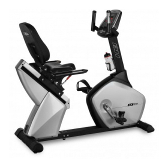
- Page 1 LK570 OWNER’S MANUAL Important: Read all instructions carefully before using this product. Retain this owner’s manual for future reference. BH North America | 20155 Ellipse, Foothill Ranch, California 92610 | p.949.206.0330 | f.949.206.0013 | www.BHFitnessUSA.com...
-
Page 2: Table Of Contents
TABLE OF CONTENTS Title Page Introduction Warnings and Labels Safety Information Exercise Instruction Training Guidelines Suggested Stretches Assembly Instructions Console Operations Maintenance and Cleaning Exploded View Drawing Parts List Warranty... -
Page 3: Introduction
CONGRATULATIONS Congratulations on your purchase of BH Fitness equipment. We hope you appreciate the style, quality, and value that exercisers around the world have come to expect from BH Fitness. If you have any questions, concerns or product issues please call our Customer Service Team at 1-866-325-2339 or email us at CustomerSupport@BHNorthAmerica.com. -
Page 4: Warnings And Labels
WARNINGS AND LABELS... -
Page 5: Safety Information
6. This machine must only be used for the purposes described in this manual. DO NOT use accessories that are not recommended by BH Fitness. Read manual prior to use and follow all warnings and instructions. 7. Do not place sharp objects near the machine. -
Page 6: Exercise Instruction
EXERCISE INSTRUCTION Use of the machine offers various benefits; it can improve fitness, muscle tone and when used in conjunction with a calorie controlled diet, it can help you lose weight. 1. Consult your doctor before starting any exercise program. It is advisable to undergo a complete physical examination. -
Page 7: Training Guidelines
TRAINING GUIDELINES Exercise is one of the most important factors in the overall health of an individual. Listed among its benefits are: • Increased capacity for physical work (strength endurance) • Increased cardiovascular (heart and arteries/veins) and respiratory efficiency • Decreased risk of coronary heart disease •... - Page 8 OXYGEN UPTAKE The effort that you can exert over a prolonged period of time is limited by your ability to deliver oxygen to the working muscles. Regular vigorous exercise produces a training effect that can increase your aerobic capacity by as much as 20 to 30%. An increased VO2 Max indicates an increased ability of the heart to pump blood, of the lungs to ventilate oxygen, and of the muscles to take up oxygen.
- Page 9 HEART RATE As you exercise, your heart beat increases. This is often used as a measure of the required intensity of an exercise. You need to exercise hard enough to condition your circulatory system, and increase your pulse rate, but not enough to strain your heart. Your initial level of fitness is important when developing an exercise program for you.
- Page 10 MUSCLE SORENESS For the first week or so, muscle soreness may be the only indication you have that you are on an exercise program. This, of course, does depend on your overall fitness level. A confirmation that you are on the correct program is a very slight soreness in most major muscle groups. This is quite normal and will disappear in a matter of days.
-
Page 11: Suggested Stretches
SUGGESTED STRETCHES Head Rolls Rotate your head to the right for one count while feeling the stretch up the left side of your neck. Next, rotate your head back for one count, stretching your chin to the ceiling. Rotate your head to the left for one count, and finally, drop your head to your chest for one count. - Page 12 SUGGESTED STRETCHES Inner Thigh Stretch Sit with the soles of your feet together with your knees pointing outward. Pull your feet as close into your groin as possible. Gently push your knees towards the floor. Hold for 15 counts. Toe Touches Slowly bend forward from your waist, letting your back and shoulders relax as you stretch toward your toes.
-
Page 13: Assembly Instructions
ASSEMBLY INSTRUCTIONS... - Page 14 STEP 1 FRONT STABILIZER ASSEMBLY Attach the front stabilizer (B) to the main frame (A1). Line up the mounting holes and secure them with bolts (N8), spring washers (N2) and washers (N3). STEP 2 REAR STABILIZER ASSEMBLY Attach the rear stabilizer (C) to the main frame (A2), secure them with bolts (N4), spring washers (N2) and washers (N3).
- Page 15 STEP 3: FRONT AND REAR MAIN FRAME ASSEMBLY Mate the hand pulse sensor connector (A24) to (A23) and the power cable (A31) to (A32). Then slide the front and rear main frames together (being careful to avoid pinching the wires) and secure the joint with screws (N1), spring washers (N2) and washers (N3). STEP 4 UPRIGHT INSTALLATION Slide the upright tube (D) through the plastic cover...
- Page 16 STEP 5 SEAT SLIDER RELEASE HANDLE AND RIGHT HANDLE BAR ASSEMBLY Mate the hand pulse sensor connector (A32) to (J1) and mount the right handle bar (J-(R)) to the matching holes on the base slider (A9) and fix with bolts (N7). Insert the slider handle (A11) into the round peg and use set screw (N10) to fix it in place.
- Page 17 STEP 7 BACKREST AND BOTTLE CAGE ASSEMBLY Place backrest cushion (H) against the backrest tube (A10) and attach with washers (N17) and hex screws (N6). Next place the bottle cage (K1) along the hole pattern on the upright tube (D) and tighten with screws (K3). (Note: Do not over tighten) STEP 9 STEP 8 CONSOLE ASSEMBLY...
- Page 18 STEP 10 PEDAL ASSEMBLY Install the strap onto each pedal. Thread the right pedal (L-R) onto the right crank. Secure in place by tightening clockwise. (Note: the right pedal is marked with an “R”) Next, thread the left pedal (L-L) onto the left crank.
- Page 19 STEP 12 SEAT ADJUSTMENTS Push the seat slide adjustment handle (A11) forward/down, then slide the seat back or forth as desired. Pull the adjustment handle back up to lock the slider in place. STEP 13 BACKREST ADJUSTMENTS Backrest position is controlled by a pneumatic cylinder which can be activated to change the backrest angles.
- Page 20 STEP 14 MOVING THE MACHINE The front stabilizer has built-in transportation wheels. Stand at the rear of the machine and lift it up until the weight of the machine is transferred to the wheels. Push or pull to move the machine to a new location, and then carefully lower the rear of the machine down.
-
Page 21: Console Operations
CONSOLE OPERATIONS... - Page 22 SPECIFICATIONS: MODE To confirm all setting values RESET To reset all parameters to default value START/STOP To start or stop training To make upward setting change DOWN To make downward setting change RECOVERY In stop or start mode, pressing this button will start Heart Rate recovery status measurement.
- Page 23 Pedaling action charges the battery as well. The battery is used by the system to maintain console operations while workout statistic reporting is taking place after the pedals stop spinning. 1. MANUAL MODE User may preset their own resistance level from 1 to 16 by pressing the UP/DOWN buttons.
-
Page 24: Maintenance And Cleaning
MAINTENANCE AND CLEANING Care has been taken to assure that your hybrid bike has been properly adjusted and lubricated at the factory. It is not recommended that the user attempt service on the internal components. Instead, seek service from an authorized service center. However, you may clean the outer surface. -
Page 25: Exploded View Drawing
EXPLODED VIEW DRAWING... -
Page 26: Parts List
PARTS LIST To order replacement parts: provide your customer service representative with the product model number and the part number located on the Parts List below, along with the quantity you require. DESCRIPTION Q'TY DESCRIPTION Q'TY DESCRIPTION Q'TY A1 FRONT MAIN FRAME A15-8 WASHER E1-1 LEFT HANDLEBAR COVER(L) A2 REAR MAIN FRAME... -
Page 27: Warranty
For more detailed warranty information or to register your product warranty easily online, visit our website at: www.BHFitnessUSA.com FOR WARRANTY REPAIRS, PLEASE DO NOT TAKE YOUR MACHINE BACK TO THE RETAIL STORE. CONTACT BH FITNESS FIRST. BH North America Corporation 20155 Ellipse Foothill Ranch, CA 92610 Phone: 949.206.0330;...
Need help?
Do you have a question about the LK570 and is the answer not in the manual?
Questions and answers