Table of Contents
Advertisement
Quick Links
Installation, Operation and Maintenance Manual
Installation, Operation and Maintenance Manual
Please read and save these instructions. Read carefully before attempting to assemble, install, operate or maintain the
Please read and save these instructions. Read carefully before attempting to assemble, install, operate or maintain the
product described. Protect yourself and others by observing all safety information. Failure to comply with instructions
product described. Protect yourself and others by observing all safety information. Failure to comply with instructions
could result in personal injury and/or property damage! Retain instructions for future reference.
could result in personal injury and/or property damage! Retain instructions for future reference.
Model XGH2O
General Safety Information
Only qualified personnel should install this unit.
Personnel should have a clear understanding of these
instructions and should be aware of general safety
precautions. Improper installation can result in electric
shock, possible injury due to coming in contact with
moving parts, as well as other potential hazards. Other
considerations may be required if seismic activity
is present. If more information is needed, contact a
licensed professional engineer before moving forward.
1. Follow all local electrical and safety codes, as well
as the National Electrical Code (NEC), the National
Fire Protection Agency (NFPA), where applicable.
Follow the Canadian Electric Code (CEC) in
Canada.
DANGER
Always disconnect power before working on or
near a unit. Lock and tag the disconnect switch or
breaker to prevent accidental power up.
CAUTION
When servicing the unit, motor may be hot enough
to cause pain or injury. Allow motor to cool before
servicing.
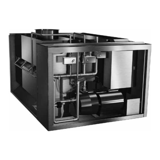
Grease Grabber™ H
Auto-Cleaning Hood
Model XGH20 Grease Grabber Auto-Cleaning Hood
Part #473381
O
2
1
Advertisement
Table of Contents

Related Manuals for Accurex Grease Grabber H2O XGH2O


Summary of Contents for Accurex Grease Grabber H2O XGH2O
- Page 1 Part #473381 Grease Grabber™ H Auto-Cleaning Hood Installation, Operation and Maintenance Manual Installation, Operation and Maintenance Manual Please read and save these instructions. Read carefully before attempting to assemble, install, operate or maintain the Please read and save these instructions. Read carefully before attempting to assemble, install, operate or maintain the product described.
- Page 2 Receiving The unit should be stored at least 3½ in. (89 mm) off the floor on wooden blocks covered with moisture Upon receiving the product check to make sure all proof paper or polyethylene sheathing. Aisles between items are accounted for by referencing the bill of parts and along all walls should be provided to permit lading to ensure all items were received.
-
Page 3: Table Of Contents
Grease Grabber™ H2O System Function Grease Grabber™ H O System Function ....3 Cleaning Cycle Accurex XGH2O hoods are designed for three primary Manual and Automatic Engagement ......4 functions: Fire Mode ..............4 • Capture and contain the effluent produced by the System Components cooking process. -
Page 4: Cleaning Cycle
Cleaning Cycle Fire Mode In the event of a fire, the hood exhaust fan(s) will turn Manual Engagement on at full power and the supply fan will turn off (default The wash function is triggered by pressing the Clean setting controlled by others) regardless of current fan Hood button after the exhaust fans are shut down at operation. -
Page 5: System Components Hood
FAN 100% button for sending fan speeds to 100%. For detailed information on the Vari-Flow Air The recirculation pump is shipped loose with the Management system, please refer to the Accurex hood. See pages 16 for installation details. website, www.accurex-systems.com... -
Page 6: Unpacking
Skid Front Lifting Unpacking Skid Hood Width and Base Weights Front Lifting Base Weight Base Weight Skid Hood Width without Water with Water inches lbs. lbs. (cm) (kg) (kg) Remove side, back Profile of Hood Profile of Hood and top lumber. (121.92) (199.58) (221.35) -
Page 7: Installation Overview Filler Panels
Installation Overview NOTE Filler Panels If you have a Back Supply Plenum (BSP), this must be installed before the hood. Refer to page 11 for 1. Unpack the hood and lay it on the lifting skid. instructions on installing the BSP. 2. -
Page 8: Hood Hanging Height
UL label located on the inside of the hood on the end panel. The hood must be hung level to operate Accurex does not recommend walking or standing properly. on the hood top as damage can result. If you... -
Page 9: Ductwork
Ductwork Installing External Supply Plenums Exhaust Option #3 Option #2 Threaded Rod Uni-Strut supplied by others As specified in NFPA 96, Ch. 7.5 (latest edition), supplied by others Threaded Rod exhaust duct systems must be constructed in the TOP VIEW following manner: HOOD Materials: Ducts shall be constructed of and... -
Page 10: Uni-Strut
BACKSUPPLY CANOPY STYLE HOOD BACKSUPPLY CANOPY STYLE HOOD BACKSUPPLY BACKSHELF HOOD Using the Uni-Strut - Option #2 Using the Threaded Rod - Option #3 1. The uni-strut (supplied by others) that holds the 1. Insert 1/2 in. (12.7 mm) diameter threaded rod (by hood up, cantilevers over the end of the hood and others) into hanger brackets on the supply plenum is mounted to the supply plenum hanger brackets. -
Page 11: Ul Listed Fastener
Using the UL Listed Fastener Provided 3. If the back supply plenum is greater than 9 ft. 10 in. (299.72 cm) long, divide the length of the 1. Drill a 9/32 in. hole for the 1/4 in. bolt from the back supply by four. -
Page 12: Hanging The Hood
6. Fasten the back supply to the wall, going through 5. Connect the remaining ductwork for the back the lower back supply wall. supply and the hood. It is recommended that caulk be applied at the mating seams and • These fasteners are to help maintain the location surfaces of the back supply, the hood, and the Canopy Style Hood of the Back Supply, and are not intended to hold... -
Page 13: Enclosure Panels
Installing Enclosure Panels Installing End Skirts Before installing the enclosure panels, make sure 1. After the hood is hung in position, slide the the hood is hung in position with all the ductwork hemmed form on top of the end skirt onto the end attached, electrical connections and fire system panels of the hood. -
Page 14: Backsplash Panels
Installing Backsplash Panels 1. After the hood is hung in position, slide the flat AT BACKSPLASH PANEL flange of the backsplash panel behind the back of RIAL GAUGE — STAINLESS Flat backsplash panel the hood. Material gauge – Stainless Note: If the backsplash panel length is greater LAT BACKSPLASH PANEL than 45 in. -
Page 15: Duct Collar
Installing Duct Collar Overview of exhaust and supply plenum locations TOP VIEW Hanger Bracket Exhaust Duct Connection Exhaust Plenum 14.0 Exhaust duct connection is to be a continuous liquid-tight weld to hood. Hood Width Duct cut out area Front of Hood Hood Length BACK VIEW Supply Duct... -
Page 16: Plumbing
Plumbing Plumbing Connections Once the hood is hung, the recirculation pump and detergent tank (both shipped loose) must be installed in the controls cabinet. Pump Installation • Remove bolts from pump mounting plate in cabinet. • Place the pump on the isolators located on the mounting plate with the bolts removed. -
Page 17: Detergent Tank
Electrical Detergent Tank Installation The detergent tank is located as shown in the photo. Electrical Wiring When installing the detergent tank, the low detergent All wiring must be done according to NEC (National indicator float and the detergent pump inlet tubing will Electrical Code NFPA #70) and local building codes. -
Page 18: Timer Programming - 24 Hour / 7 Day Programming / Operation
Timer Programming – 24 Hour / 7 Day Reviewing Events Programmed Setting the Clock In your current time display, press the PROG (program) button repeatedly to check your settings. 1. Press and hold the CLOCK button. 2. Press and hold the DAY button until the display When finished, press the CLOCK button to return the shows the current day. -
Page 19: Initial System Start-Up
Initial System Start-Up Daily Operation of the XGH2O Hood Pressing the FAN ON/OFF button will start/stop the 1. Check electrical power (see wiring diagram) exhaust and supply fans if interlocked. • Correct supply voltage Pressing the HOOD LIGHTS button will turn on/off the •... -
Page 20: Sequence Of Operation
20 minute dry time Shut OFF exhaust fan(s) Stage 8: Rinse primary filters SEQUENCE OF OPERATION - GREASE GRABBER H2O Detergent pump OFF Turn OFF exhaust fan(s) Stage 1: Sequence of Operation - Grease Grabber™ H Fill hood tank (hot water) Spray for 5 minutes Wash, rinse &... -
Page 21: Airflow Testing Procedure
Airflow Testing Procedure After the appropriate number of readings have been taken from the inlet slot of the hood, an average reading can be calculated by summing the velocity readings and dividing the total value by the number of readings taken. Sum of Velocity Readings Average Velocity Number of Readings... -
Page 22: Amerex
Amerex® Wiring Plan View POWER SOURCE MANUAL RESET RELAY ELECTRIC GAS VALVE MICROSWITCH INSTALLER PROVIDED JUNCTION BOXES BASIC WIRING DIAGRAM POWER SOURCE MANUAL RESET RELAY RED (COMMON) YELLOW (N.O) BLACK (N.C.) GAS VALVE NOTE: DO NOT USE YELLOW WIRE ON MICROSWITCH IN NORMAL MICROSWITCH INSTALLATION. -
Page 23: Ansul
TYPICAL WIRING SCHEMATIC ELECTRIC EQUIPMENT SHUTDOWN ANSUL file name: Typicalwiringschematicelectricgasshut-offvalveshutdowndetail.ai / File received on August 4, 2010 Ansul® Wiring Plan View TYPICAL WIRING SCHEMATIC ELECTRIC EQUIPMENT SHUTDOWN ANSUL SNAP-ACTION SWITCH BLACK (SWITCH CONTACTS SHOWN WITH ANSUL AUTOMAN IN THE COCKED POSITION) BROWN ANSUL SNAP-ACTION SWITCH BLACK... -
Page 24: Wiring Diagram
LADDER DIAGRAM, CAD DRAWING NO. REV. Wiring Diagram GGH2O PART NO. IAN31295 P.O.BOX 410 SCHOFIELD, WISCONSIN 54476-0410 473596 Wiring diagram is located on the inside cover of the control cabinet located on the end of the hood. 3POLE 32 AMPS 120VAC 1PH. -
Page 25: Maintenance
Maintenance Floats Capture Tank The interior surfaces of the hood capture tank should The floats need to be be wiped down weekly. inspected two weeks after start-up and then once a Filters month thereafter. The Grease Grabber filters (bead filters) require The float can be inspected visually inspection (not removed from hood) two by first turning the... -
Page 26: Troubleshooting
See the chart below to identify the Detergent tank — is it empty or filled with wrong replacement parts needed. detergent? Accurex Grainger® Detergent pump — is the detergent pump running? Part Part Is there power to the pump? Is the detergent level... -
Page 27: Grease Grabber H 2 O Start-Up Checklist
Grease Grabber™ H 2 O Start-Up Checklist Wash Mode Check boxes when item has been verified and gone over with customer. • See sequence of operations on page 20. Hook-Up • If using 24 hour / 7 day timer, wash cycle will start at scheduled time after “Fan On/Off”... -
Page 28: Maintenance Log
Warranty Accurex warrants this equipment to be free from defects in material and workmanship for a period of one year from the shipment date. Any units or parts which prove defective during the warranty period will be replaced at our option when returned to our factory, transportation prepaid.
Need help?
Do you have a question about the Grease Grabber H2O XGH2O and is the answer not in the manual?
Questions and answers