Table of Contents
Advertisement
Quick Links
Installation, Operation and Maintenance Manual
Please read and save these instructions for future reference. Read carefully before attempting to assemble,
install, operate or maintain the product described. Protect yourself and others by observing all safety
information. Failure to comply with instructions could result in personal injury and/or property damage!
Model XMPX
General Safety Information
Only qualified personnel should install and maintain
this system. Personnel should have a clear
understanding of these instructions and should
be aware of general safety precautions. Improper
installation can result in electric shock, possible injury
due to coming in contact with moving parts, as well as
other potential hazards. Other considerations may be
required if high winds or seismic activity are present.
If more information is needed, contact a licensed
professional engineer before moving forward.
1. Follow all local electrical and safety codes, as
well as the National Electrical Code (NEC), the
National Fire Protection Agency (NFPA), where
applicable. Follow the Canadian Electric Code
(CEC) in Canada.
2. All moving parts must be free to rotate without
striking or rubbing any stationary objects.
3. Unit must be securely and adequately grounded.
4. Do not spin wheel faster than maximum
cataloged fan RPM. Adjustments to fan speed
significantly affect motor load. If the fan RPM is
changed, the motor current should be checked
to make sure it is not exceeding the motor
nameplate amps.
5. Verify that the power source is compatible with
the equipment.
6. Never open access doors to the unit while it is
running.
DANGER
• Always disconnect power before working on or
near this equipment. Lock and tag the disconnect
switch or breaker to prevent accidental power up.
• If this unit is equipped with optional gas
accessories, turn off gas supply whenever power
is disconnected.
CAUTION
This unit is equipped with a compressed refrigerant
system. If a leak in the system should occur,
immediately evacuate and ventilate the area. An
EPA Certified Technician must be engaged to make
repairs or corrections. Refrigerant leaks may also
cause bodily harm.
CAUTION
When servicing the unit, the internal components
may be hot enough to cause pain or injury. Allow
time for cooling before servicing.
Model XMPX Make-Up Air Unit
Part #475084
Model XMPX
Model MPX Make-Up Air Unit
1
Advertisement
Table of Contents
Troubleshooting

Related Manuals for Accurex XMPX Series


Summary of Contents for Accurex XMPX Series
-
Page 1: General Safety Information
Part #475084 Model XMPX Installation, Operation and Maintenance Manual Please read and save these instructions for future reference. Read carefully before attempting to assemble, install, operate or maintain the product described. Protect yourself and others by observing all safety information. Failure to comply with instructions could result in personal injury and/or property damage! Model XMPX General Safety Information Only qualified personnel should install and maintain... -
Page 2: Receiving, Handling And Storage
Receiving should be given to touch-up or repainting. Units with special coatings may require special techniques for Upon receiving the product, check to make sure all touch-up or repair. items are accounted for by referencing the Bill of Lading to ensure all items were received. Inspect Machined parts coated with rust preventative should each crate for shipping damage before accepting be restored to good condition promptly if signs of... -
Page 3: Table Of Contents
Table of Contents General Safety Information ....1 Typical Wiring Diagram ....14-15 Receiving, Handling and Storage ... 2 Controller Sequence of Operation . -
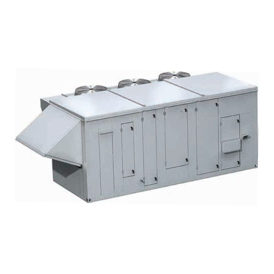
Page 4: Product Overview
Product Overview MPX Subassemblies This model is a horizontally configured make-up Blower air unit designed for outdoor installations. It has Each unit has just one backward curved blower an integral DX package for cooling and optionally (centrifugal fan). For further information refer to the contains either an electric heater or one or two highly Plenum and Plug IOM. -
Page 5: Unit Weights And Dimensions
Unit Weights and Dimensions - dimensions are in inches MPX-H14, MPX-H24 4-INCH FILTERS SUPPLY AIR REHEAT CONTROL BLOWER IG HEATER DAMPER COIL COIL CENTER ASSEMBLY 2 INCH FILERS SUPPLY AIR WEATHERHOOD 2 INCH SUPPLY AIR FILTERS COMPRESSOR TOP VIEW ELEVATION MPX-H34 4-INCH FILTERS... -
Page 6: Service Clearances
Service Clearances The units require minimum clearances for access on Lifting all sides for routine maintenance. Filter replacement, 1. Before lifting, be sure that all shipping material drain pan inspection and cleaning, fan bearing has been removed from unit. lubrication and belt adjustment are examples of 2. -
Page 7: Rail And Roof Curb Mounting Rail Mounting And Layout
Ductwork Connections Rail and Roof Curb Mounting The supply fan in this unit is a plenum-type fan. The Rail Mounting and Layout discharge opening dimensions are provided in the • The unit may be installed on rails provided and chart below. For proper fan performance, match the installed by others. -
Page 8: Vibration Isolators
Vibration Isolators Plumbing / Piping Overview The only piping connections required are the NOTE condensate drain trap and gas connections for the Many motor / blower assemblies include optional optional gas furnace(s). spring vibration isolation devices. When these Condensate Drain Trap isolation springs are used, the motor / blower This unit is equipped with a stainless steel condensate assembly is secured for shipment by compressing... -
Page 9: Electrical Information
Electrical Information Key: V1, V2, V3 = line voltages as measured VA (average) = (V1 + V2 + V3) / 3 The unit must be electrically grounded in accordance VD = Line voltage (V1, V2 or V3) that with the current National Electrical Code, ANSI/NFPA deviates farthest from average (VA) 70. -
Page 10: Discharge Air Temperature Sensor
Discharge Air Temperature Sensor Recommended Electrical and Gas Connection Locations All units are supplied with a Discharge Air Temperature Sensor that is to be field-installed prior to unit start- Installation requires penetrations into the cabinet for up. The sensor is to be installed at least three duct high voltage electrical supply, low voltage controller diameters downstream of the circuitry and for gas supply. -
Page 11: Control Centers
Control Centers Furnace Control Center Components (component locations will vary) Each model has a main control center where high Components shown are for a typical 4:1 turndown voltage supply wiring and low voltage controller configuration. circuitry is terminated. In addition, if the electric heat option was selected, there will be a separate control center for the electric heater where the dedicated high voltage supply is terminated. -
Page 12: Control Center Components Ddc Control Package
Control Center Components DDC Control Package Fan Proving Switch The unit uses a pressure switch to prove fan operation before operating any heating or cooling sequence. It does this by verifying a difference in air pressure on both sides of the air supply fan. While the operation of the switch is verified at the factory, the pressure switch should be adjusted to meet field conditions. -
Page 13: Variable Frequency Drives (Vfd)
Variable Frequency Drive (VFD) An optional VFD may be installed at the factory for purposes of controlling the speed of the blower motors. Its purpose is to constantly regulate the speed of the blower motor, in response to various optional sensors. When the VFD receives a predetermined signal, it will Typical Variable... -
Page 14: Typical Wiring Diagram
Typical Wiring Diagram This is a typical wiring diagram for this unit. A model-specific wiring diagram is attached to the inside of the control center door of each unit. The wiring diagram includes a legend highlighting which accessories or options are provided by the factory. - Page 15 COMPRESSOR/CONDENSER FAN CONTROL COMPONENTS LOCATED IN COMPRESSOR COMPARTMENT LPS1 HPS1 ® LPS2 HPS2 FCS1 LT BL Wiring Diagram Code: GI1CA61B2A02D31AP01 FCS2 LT BL CAUTION UNIT SHALL BE GROUNDED IN ACCORDANCE WITH N.E.C. POWER MUST BE OFF WHILE SERVICING. NOTES USE COPPER CONDUTORS ONLY 60°...
-
Page 16: Controller Sequence Of Operation
Direct Digital Control (DDC) Cooling Sequence The DDC controller will power the compressed Sequence of Operation refrigerant system to maintain the supply temperature Microprocessor Controller set point. The mechanical cooling will be locked out when the outside air is less than 55° - 2°F hysteresis, This unit is adjustable. - Page 17 Building Freeze Protection If the supply air temperature drops below 35°F (adjustable), the DDC will de-energize the unit and activate the alarm output after a preset time delay. Alarms Indication The DDC has a single digital output for remote indication of an alarm condition. Possible alarms include: •...
-
Page 18: Optional Controller Accessories
Optional Controller Accessories Microprocessor (DDC) Remote Interface This unit can be ordered with a number of optional The optional remote accessories to expand the functionality or usability of interface panel permits the DDC controller. When these options are ordered viewing of settings from the factory, the DDC controller is pre-configured that are present on the to incorporate the accessory. -
Page 19: System Components
Factory Installed Refrigeration System Components Pressure Port for Troubleshooting Valve Circuit A Condenser Coil Pressure Port for Troubleshooting Reheat Valves High Side Check Valve Pressure Drop Service Valve for Superheat and Low Side Pressure Service Valve for Subcooling Gauge/ High Side Pressure Drop 1. - Page 20 Factory Installed Components (continued) 12. Hot Gas Bypass Valve (optional) 7. Condenser Fans On units equipped with hot gas bypass, hot gas The unit is equipped with multiple direct-drive from the compressor is injected into the liquid line condensing fans. The fans provide the necessary of the evaporator coil after the TXV.
-
Page 21: Digital Scroll Compressor
Digital Scroll Compressor If the digital scroll compressor option was selected Configuration for this unit, it is equipped with a Copeland Scroll In units with more than one compressor, only the lead Digital™ compressor. compressor will be digital scroll type. Digital scroll Refrigeration Modulation compressors can be identified by the label on the compressor. -
Page 22: Electronic Control
Digital Scroll Compressors Two Compressor Operation Concept Whenever two compressors are used in a unit, the (continued) digital scroll compressor is part of refrigerant circuit Electronic Control “A”. A conventional fixed scroll compressor is used for circuit “B”. When the unit is at rest and there is no A Copeland Scroll Digital™... -
Page 23: Pre Start-Up Checklist
Pre Start-Up Checklist – complete prior to WARNING application of power All motor(s) / compressor(s) have been checked for Verify proper drain trap installation (refer to rotation. If blower rotation is incorrect, wiring must Condensate Drain section). be changed at the disconnect to ensure all motor(s) / compressor(s) are corrected. - Page 24 Start-Up Checklist Compressors Each DX unit is equipped with either one or two (continued) compressors. Each compressor is part of a separate refrigeration circuit. NOTE CIRCUIT A Refrigeration System Start-Up Checklist must be performed by a Qualified Refrigeration Technician. Compressor: If a digital scroll compressor is installed in the unit, _______ L1 amps...
-
Page 25: Unit Start-Up
Unit Start-Up Fan Performance Modifications Due to job specification revisions, it may be necessary Refer to Component section for component locations. to adjust or change the sheave or pulley to obtain the desired airflow at the time of installation. Start-up technician must check blower amperage to ensure The fan should be checked for free rotation. -
Page 26: Fan Wheel Rotation Direction
Fan Wheel Rotation Direction Spring Vibration Isolators Blower access is labeled on unit. Check for proper Verify that any optional spring vibration isolators have wheel rotation by momentarily energizing the fan. been removed. See Installation portion of this manual. Rotation is determined by viewing Coils the wheel from the drive side and Leak test the thermal system to ensure tight... -
Page 27: Troubleshooting Airflow
Troubleshooting – Airflow Test and Balance Report The Test and Balance Report (TAB) is used to determine whether the appropriate amount of outdoor air and exhaust air is being supplied and removed from a building, respectively. There are no set rules on what information must be included in a TAB report. -
Page 28: Alarms
Troubleshooting - Alarms The first step in troubleshooting the unit is to status screen on each VFD that indicates current check the on-board alarm indicators. Several of the settings and also any alarm conditions. Some alarm electronic controls in the unit monitor the system for conditions (such as a voltage spike) may disable faults and will go into alarm, shutting down the unit or the VFD, shutting off power to the connected motor. -
Page 29: Unit
Troubleshooting - Unit Symptom Possible Cause Corrective Action Blown fuse or open circuit breaker. Replace fuse or reset circuit breaker and check amps. Defective motor or capacitor. Replace. Blower fails Motor starter overloaded. Reset starter and check amps. to operate Check for On/Off switches. - Page 30 Troubleshooting - Unit Symptom Possible Cause Corrective Action Adjust wheel and/or inlet cone. Tighten wheel hub or Fan wheel rubbing on inlet. bearing collars on shaft. Replace defective bearing(s). Lubricate bearings. Bearings. Tighten collars and fasteners. Wheel out of balance. Replace or rebalance.
-
Page 31: Refrigeration System
Troubleshooting – Refrigeration Circuit TROUBLESHOOTING NOTE IMPORTANT Do not release refrigerant to the atmosphere! If Before any components are changed on the required service procedures include the adding or refrigeration system, the cause of the failure must be removing of refrigerant, the service technician must identified. - Page 32 Troubleshooting – Refrigeration Circuit Symptom Possible Cause Corrective Action Refrigerant overcharge. Check pressures, charge by subcooling. Condenser fan motor defective. Check fan motor. Compressor Condenser coil inlet obstructed or Check coil and inlet clearances. starts but dirty. cuts out Check high side equalized pressures, check thermal on high Air or non-condensables in system.
- Page 33 Troubleshooting – Refrigeration Circuit Symptom Possible Cause Corrective Action Check for high entering wet bulb temperature, check Excessive load on evaporator coil. for excessive air. Compressor is unloaded. Check digital scroll controller signal and solenoid valve. (digital scroll) Check the thermal expansion valve, ensure bulb is insulated.
- Page 34 Troubleshooting – Refrigeration Circuit Symptom Possible Cause Corrective Action Check subcooling, check for leak. Repair leak and add Insufficient refrigerant charge. refrigerant. Defective or improperly adjusted Check superheating and adjust thermal expansion expansion valve. valve. discharge pressure Low suction pressure. See “low suction pressure”.
- Page 35 Troubleshooting – Refrigeration Circuit Symptom Possible Cause Corrective Action Check airflow, check filters, check drive for loose parts Insufficient evaporator airflow. or belts. Suction line is frosting Malfunctioning or defective expansion Check bulb of thermal expansion valve. valve. Hot gas bypass valve not functioning Check valve.
-
Page 36: Routine Maintenance
Routine Maintenance 5. Blower Wheel & Fasteners Check for wear, tension, alignment Check all fasteners for tightness DANGER Check for fatigue, corrosion, wear Electric shock hazard. Can cause injury or death. 6. Bearings Before attempting to perform any service or Lubricate per the schedule in the Fan Bearings maintenance, turn the electrical power to the unit section... -
Page 37: Fan Motors
When replacing belts on multiple groove drives, all Fan Bearings belts should be changed to provide uniform drive Most bearings are permanently lubricated and require loading. Do not pry belts on or off the sheave. Loosen no further lubrication under normal use. Normal use belt tension until the belts can be removed by simply being considered -20°F to 120°F and in a relatively lifting the belts off the sheaves. -
Page 38: Internal Filter Maintenance
Internal Filter Maintenance Coil Maintenance The unit will typically be provided with 2-inch Coils must be cleaned to maintain maximum thick pleated paper filters in the airstream. These performance. Check coils once per year under normal filters should be checked according to a routine operating conditions and if dirty, brush or vacuum maintenance schedule and replaced as necessary clean. -
Page 39: Maintenance Log
Maintenance Log Date __________________ Time _____________ AM/PM Date __________________ Time _____________ AM/PM Notes:___________________________________________ Notes:___________________________________________ _________________________________________________ _________________________________________________ _________________________________________________ _________________________________________________ _________________________________________________ _________________________________________________ _________________________________________________ _________________________________________________ Date __________________ Time _____________ AM/PM Date __________________ Time _____________ AM/PM Notes:___________________________________________ Notes:___________________________________________ _________________________________________________ _________________________________________________ _________________________________________________ _________________________________________________ _________________________________________________ _________________________________________________ _________________________________________________ _________________________________________________ Date __________________ Time _____________ AM/PM... -
Page 40: Warranty
Warranty Accurex warrants this equipment to be free from defects in material and workmanship for a period of one year from the shipment date. Any units or parts which prove to be defective during the warranty period will be replaced at our option when returned to our factory, transportation prepaid.
Need help?
Do you have a question about the XMPX Series and is the answer not in the manual?
Questions and answers