Advertisement
Quick Links
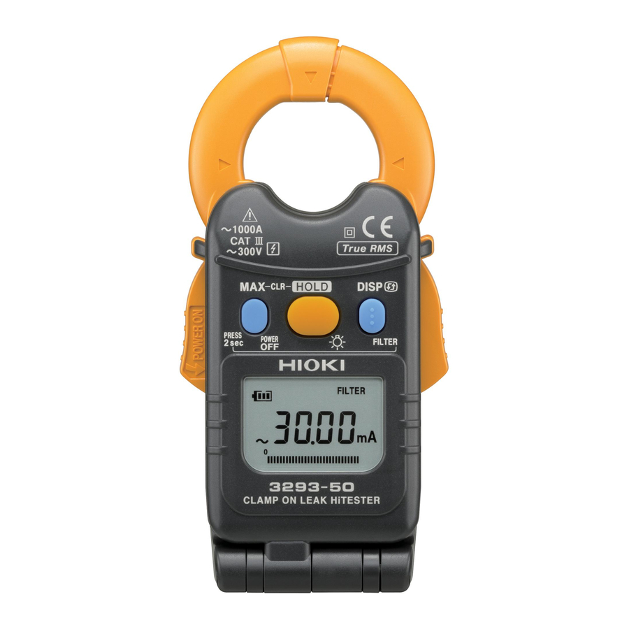
3293-50
CLAMP ON LEAK HiTESTER
Instruction Manual
January 2012 Revised edition 1
Printed in Japan
3293C981-01 12-01H
Introduction
Thank you for purchasing the HIOKI Model 3293-50 CLAMP ON LEAK
HiTESTER. To obtain maximum performance from the product, please
read this manual first, and keep it handy for future reference.
Overview
The 3293-50 Clamp On Leak HiTester is a small sized, thin-type sensor
that can measure current between a wide 1 mA to 1000 A range. In ad-
dition, the angle of the display panel can be adjusted to suit the mea-
suring location, and the back light makes the product easy to use even
in dark places.
Inspection
Initial Inspection
When you receive the product, inspect it carefully to ensure that no
damage occurred during shipping. If damage is evident, or if it fails to
operate according to the specifications, contact your dealer or Hioki
representative.
Maintenance and Service
• To clean the product, wipe it gently with a soft cloth moistened with
water or mild detergent. Never use solvents such as benzene, alco-
hol, acetone, ether, ketones, thinners or gasoline, as they can
deform and discolor the case.
• If the protective functions of the product are damaged, either
remove it from service or mark it clearly so that others do not use it
inadvertently.
• If the product seems to be malfunctioning, contact your dealer or
Hioki representative.
Safety
This manual contains information and warnings essential for
safe operation of the product and for maintaining it in safe oper-
ating condition. Before using it, be sure to carefully read the fol-
lowing safety precautions.
This product is designed to comply with IEC 61010 Safety
Standards, and has been thoroughly tested for safety
prior to shipment. However, mishandling during use
could result in injury or death, as well as damage to the
product. However, using the product in a way not
described in this manual may negate the provided safety
features. Be certain that you understand the instructions
and precautions in the manual before use. We disclaim
any responsibility for accidents or injuries not resulting
directly from product defects.
Safety Symbol
In the manual, the
symbol indicates particularly important
information that the user should read before using the instrument.
The
symbol printed on the instrument indicates that the user
should refer to a corresponding topic in the manual (marked with
the
symbol) before using the relevant function.
Indicates AC (Alternating Current).
Indicates DC (Direct Current).
Indicates that the instrument may be connected to or disconnected
from a live circuit.
Indicates a double-insulated device.
Other Symbols
Indicates a prohibited action.
Symbols for Various Standards
This symbol indicates that the product conforms to safety regula-
tions set out by the EC Directive.
WEEE marking:
This symbol indicates that the electrical and electronic appliance is
put on the EU market after August 13, 2005, and producers of the
Member States are required to display it on the appliance under
Article 11.2 of Directive 2002/96/EC (WEEE).
The following symbols in this manual indicate the relative importance
of cautions and warnings.
Indicates that incorrect operation presents an extreme hazard
that could result in serious injury or death to the user.
Indicates that incorrect operation presents a significant hazard
that could result in serious injury or death to the user.
Indicates that incorrect operation presents a possibility of
injury to the user or damage to the device.
Indicates advisory items related to performance or correct operation of
the product.
Measurement categories
This product complies with CAT III 300 V safety requirements. To ensure safe
operation of measurement products, IEC 61010 establishes safety standards
for various electrical environments, categorized as CAT II to CAT IV, and called
measurement categories.
CAT II: Primary
electrical
circuits
in
equipment connected to an AC
electrical outlet by a power cord
(portable tools, household appli-
ances, etc.)
CAT II covers directly measuring
electrical outlet receptacles.
CAT III: Primary
electrical
circuits
of
heavy equipment (fixed installa-
tions) connected directly to the distribution panel, and feeders from the
distribution panel to outlets.
CAT IV: The circuit from the service drop to the service entrance, and to the power
meter and primary overcurrent protection device (distribution panel).
Using a measurement product in an environment designated with a higher-
numbered category than that for which the product is rated could result in a
severe accident, and must be carefully avoided.
Use of a measurement instrument that is not CAT-rated in CAT II to CAT IV
measurement applications could result in a severe accident, and must be care-
fully avoided.
Usage Notes
Follow these precautions to ensure safe operation and to obtain the full
benefits of the various functions.
Do not allow the product to get wet, and do not take measure-
ments with wet hands. This may cause an electric shock.
• Do not store or use the product where it could be exposed to
direct sunlight, high temperature or humidity, or condensation.
Under such conditions, the product may be damaged and insu-
lation may deteriorate so that it no longer meets specifications.
• This instrument contains a magnetic core. The device
should not be used by anyone with a pacemaker or any other
electronic medical devices installed in his body.
Names and Functions of Parts
Clamp Sensor
Press both
• Clear MAX value
Press Once
Barrier
• Data Hold
Press Once
Press 2 sec.
• Maximum Data
• Back Light
• Instantaneous value
PRESS Once
Press 2 sec.
• Digital Display
• Power OFF
PRESS 2 sec.
Lever
• Filter OFF/ON
Display (LCD)
(Magnified View)
Alternating current (AC)
MAX
MAX value
Data hold function
FILTER Filter ON
Bar graph
Over range
* The device considers the maximum
displayed value to be the MAX value.
Battery low warning (4 levels)
Specifications
Measurement specification
• Temperature and humidity for guaranteed accuracy: 23±5°C (73±9°F),
80%RH or less.
• Guaranteed accuracy period: 1 year, or opening and closing of the
Clamp Sensor 10,000times, whichever comes first.)
• Guaranteed accuracy range: 1.00 mA or above
AC current A rms (true rms indication, Auto range)
0.05 mA or less zero-suppression
Accuracy
Guaranteed
Range
Resolution
accuracy
FILTER ON
FILTER OFF
1.00 mA to 30.00
30 mA
0.01 mA
mA
27.0 mA
300 mA
0.1 mA
to 300.0 mA
0.270 A
±1.5%rdg. ±5dgt.
6 A
0.001 A
to 6.000 A
±1.5%rdg. ±5dgt.
(45 Hz to 66 Hz)
5.40 A
(50 Hz to 60 Hz)
±3.0%rdg. ±5dgt.
60 A
0.01 A
(66 Hz to 400 Hz)
to 60.00 A
54.0 A
600 A
0.1 A
to 600.0 A
540 A
1000 A
1 A
to 1000 A
:Within ±0.1% (up to 6 A range), Within±5.0%
Effect of conductor
(greater than 60 A range)
position
(in any position based on the center of the clamp sensor)
Maximum rated voltage
: 300 Vrms, Measurement category III
to earth
(anticipated transient overvoltage 4000 V)
Crest factor
: 2.8 or less (up to 600 A), 1.68 or less (1000 A range)
Diameter of measurable
:24 mm dia. or less
conductor
:Within 0.05 × precision specification / °C
Temperature coefficient
Other than 23°C±5°C (73°F±9°F)
Magnetic field
: Maximum 7.5 mA in an external magnetic field of
interference
AC 60 Hz 400 A/m (up to 6 A range)
Response time
:1.1 sec. or less
Maximum input current
:1000 A (Refer to Fig. 1)
We define measurement tolerances in terms of rdg. (reading) and dgt. (digit) val-
ues, with the following meanings:
rdg. (reading or displayed value)
The value currently being measured and indicated on the measuring product.
dgt. (resolution)
The smallest displayable unit on a digital measuring product, i.e., the input value
that causes the digital display to show a "1" as the least-significant digit.
Example
Calculation
(A) Reading error (± %rdg.): ± 1.5% of 30.00 A =
Accuracy spec
:±1.5%rdg. ±5dgt.
± 0.45 A
Measurement range:60.00 A
(B) Digit error (± dgt.): ± 5dgt. =± 0.05 A (Due to
Measurement values:30.00 A
minimum resolution of 0.01 A)
(C)Total error: (A)+(B) = ± 0.50 A
The limit error value for the measured value of
30.00 A is 29.50 A ~ 30.50 A based on the total
error (C).
General Specifications
Display update rate
1.1 sec. or less
Display
LCD: monochrome, 91 segments
Operating
0 to 40°C (32 to 104°F), 80%RH or less
temperature and
(with no condensation)
humidity
Storage temperature
-10 to 50°C (14.0 to 122.0°F), 80%RH or less
(with no condensation)
and humidity
Location for use
Indoors, Pollution degree 2, Altitude up to 2000 m (6562 feet)
Rated supply voltage 3 VDC × 1
Maximum rated
25 mVA
power
Power supply
CR2032 x 1 Lithium battery
Approx.18 hours
Battery lifetime
(continuous, no load, at 23°C)
Dimensions
Approx. 50W × 130H × 26D mm (1.97"W×5.12"H×1.02"D)
Mass
Approx. 135 g (4.8 oz.)
3536 Vrms /15sec.
Dielectric strength
5 mA sensitivity current between the chassis and clamp core
Safety
EN61010
Applicable standards
EMC
EN61326
9757 Carrying Case, Strap, Instruction Manual,
Accessories
CR2032 Lithium battery
Functions
ON : Grasping the lever and opening wide the Clamp
Power supply control
Sensor (sideways).
OFF: Press POWER OFF key for 2 seconds or longer.
Details of operation: Low pass filter OFF/ON
Cutoff frequency :180 Hz±30 Hz (-3dB)
Initial setting: ON (Always ON when the power supply is
turned on; non-filtered data is not saved)
Filter
Activate/De-activate: Press FILTER key for 2 seconds
or longer.
*When set to ON, the filter removes noise and other
unwanted frequency components.
Details of operation: Holds measured values (data
update is halted)
Data hold
Activate: Pressing the
key once.
De-activate:Pressing the
key once.
FILTER OFF/ON
Details of operation: Displays the maximum measured
values reached since the power has been turned on.
MAX value display
Activate/De-activate: Pressing the MAX key once.
Clear displayed maximum value: Press the MAX key and
HOLD key at the same time. Filter OFF/ON
Details of operation: The power cuts off when "0" is
displayed continuously for 1 minute.
Auto power-off
Any key operation is not performed for approx.10 minutes.
To de-activate: Power ON while pressing the
Details of operation: Displays 4 levels of remaining
Battery Level
battery charge.
Indicator
*Refer to "Replacing Battery".
Setting method: Press
key for 2 seconds or longer.
Back light
(About 15 seconds lighting.)
*Frequent use of backlight reduces battery life.
Details of operation: Automatically reverses when the
Liquid crystal display
display panel is opened and closed.
(LCD) reversal
Manual reversal: Pressing the
key once.
*Refer to "Opening and Closing the Display Panel".
Shows the proportion of the measured value to the
Bar graph
range.
Over-Range Display: Displays "OVER" when a high
crest factor current is inputted, which means an out of
Over range display
the accuracy guarantee.
*Refer to "Crest factor".
Measurement Procedure
Pre-Operation Inspection
(Check the following before using the product.)
• Before using the product the first time, verify that it operates
normally to ensure that the no damage occurred during stor-
age or shipping. If you find any damage, contact your dealer
or Hioki representative.
• The clamp sensor or the case shall be free of damage. (If
damage has occurred, avoid using the product. Use of the
product under these conditions may result in electric shock.)
• The mating portions of the clamp sensor should be free of
any scratches or cracks.
• Battery power should be near full capacity when power is turned
on. (Refer to "Replacing Battery".)
• The reading should be around 0 A using the current function
when no measurements are being made.
key.
Advertisement

Subscribe to Our Youtube Channel
Related Manuals for Hioki 3293-50


Summary of Contents for Hioki 3293-50
-
Page 1: Specifications
Activate: Pressing the key once. equipment connected to an AC 80%RH or less. The 3293-50 Clamp On Leak HiTester is a small sized, thin-type sensor De-activate:Pressing the key once. electrical outlet by a power cord • Guaranteed accuracy period: 1 year, or opening and closing of the that can measure current between a wide 1 mA to 1000 A range. -
Page 2: Error Display
(2) When using the 3293-50 to measure special waveforms, • Put the conductor perpendicular to the sensor, as shown in the sketch. such as those on the secondary side of an inverter •...
Need help?
Do you have a question about the 3293-50 and is the answer not in the manual?
Questions and answers