Table of Contents
Advertisement
Quick Links
Advertisement
Table of Contents

Subscribe to Our Youtube Channel
Related Manuals for AMF-BRUNS AL1


Summary of Contents for AMF-BRUNS AL1
- Page 1 Operating Instructions LINEAR LIFT AL1 www.amf-bruns.de...
- Page 3 Contact our customer service department to order spare parts or accessories. The spare parts catalogue can be found in the service section of our Internet site (see Chapter 15, page 70). Linear Lift AL1 Page 3 of 72...
- Page 4 ...contains general notes and useful information..gives a reference to important information in other sections and documents. Some text passages serve a special purpose. These are identified as follows: Lists. Instructional text, e.g. a sequence of activities. Page 4 of 72 Linear Lift AL1...
- Page 5 Foreword Meaning of directions: If directions are given in the text (in front of, front, behind, rear, right, left), these directions relate to the normal direction of travel of the vehicle. Linear Lift AL1 Page 5 of 72...
-
Page 6: Table Of Contents
Service life of components ........35 7.2.2 Maintenance schedule ..........35 7.2.3 Maintenance record ..........35 7.3 Functional Test of the Safety Devices ........ 36 7.4 Inspection of the Hydraulic Hoses........36 Page 6 of 72 Linear Lift AL1... - Page 7 12.1 Inspection Log Master Data Sheet ........57 12.2 Inspection List ..............58 12.3 Inspection Results .............. 59 13 Electrical Circuit Diagrams ........... 67 14 Hydraulic Circuit Diagram ..........69 15 Customer Service ............70 16 Declaration of Conformity ..........71 Linear Lift AL1 Page 7 of 72...
-
Page 8: Safety
Unless of course the person in the wheelchair is also the driver of the vehicle. Proper use also includes strictly adhering to the information given in these Operating Instructions. Page 8 of 72 Linear Lift AL1... -
Page 9: Improper Use
Transportation, installation, commissioning, maintenance, repair, fault finding and disposal of the linear lift must only be carried out by persons with the corresponding technical training and experience. Linear Lift AL1 Page 9 of 72... -
Page 10: Product Monitoring
Please contact AMF-Bruns GmbH & Co. KG immediately if faults or problems are encountered when operating your linear lift or if ac- cidents or "near-misses" occur. AMF-Bruns will effect a solution to the problem with your help and the knowledge gained will flow into future projects. NOTE Guarantee work on the linear lift must only be carried out with the prior agreement of AMF-Bruns GmbH &... -
Page 11: Safety Devices
DIN EN 75078. To prevent dangers in road traf- fic, the linear lift must be equipped with warning lights or warning markings. Linear Lift AL1 Page 11 of 72... - Page 12 Use only original spare parts or spare parts which have been ap- proved of by the manufacturer. If non-original or unauthorised re- placement parts are used, this will render the guarantee null and void. Page 12 of 72 Linear Lift AL1...
-
Page 13: Description
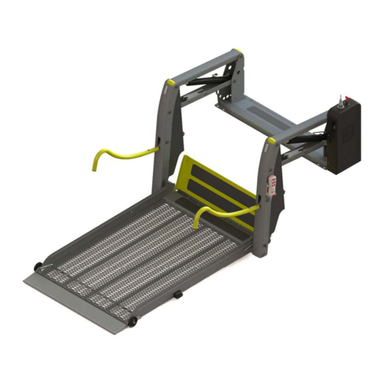
Layout and Function Carrier arms Blinkers (optional) Carrier struts Switch box with hydraulic pump Guardrails Remote control Transfer plate Roll-off guard Platform Side roll-off guards Figure 1: linear lift AL1 Solid, Overview Linear Lift AL1 Page 13 of 72... -
Page 14: Platform
Figure 2: linear lift AL1 Solid, Embarkation and Disembarkation Level The linear lift AL1 Solid has a one-piece platform. The platform of the linear lift AL1 Panorama is made up of two sections such that it is shortened when folded up to the stowed position. - Page 15 (see Figure 3 and Figure 4). Platform Figure 3: linear lift AL1 Panorama, Overview Platform Figure 4: linear lift AL1 Panorama, Stowed Position Linear Lift AL1 Page 15 of 72...
-
Page 16: Transfer Plate
Description The platform of the linear lift AL1 Split is split lengthwise. When it is stowed in the driving position, the two halves of the platform separa- te (see Figure 5). Because of this, it is possible to enter and leave the vehicle by way of the door in which the linear lift is installed, even though the linear lift is in the vertical, stowed position. -
Page 17: Hydraulic System
A rating plate, which contains the fundamental data, is attached to the linear lift (see Figure 6). The rating plate is located on the floor anchorage. Year of manufacture Designation Version Load bearing Serial number capability Manufacturer Figure 6: Rating Plate Linear Lift AL1 Page 17 of 72... -
Page 18: Technical Data
Description Technical Data Designation Linear Lift AL1 Type / Lifting platform Solid 1065 Solid 1130 Solid 1200 Solid 1380 Panorama 1200 Panorama 1400 Split 1085 Split 1085 S Split 1300 Weight 133 kg ± 10 Permissible operating pressure 92 bar Permissible number of persons on the platform max. -
Page 19: Operating Controls
Description Operating Controls Figure 7: Operating Controls on the Remote Control Figure 8: Operating Controls on the Hydraulic Pump Linear Lift AL1 Page 19 of 72... - Page 20 Raises the linear lift to the vertical, sto- “FOLD” wed position. Battery isolation Interrupts the power supply to the hyd- switch raulic pump motor. Circuit breaker Trips when a fault occurs and renders the remote control inoperative. Page 20 of 72 Linear Lift AL1...
-
Page 21: Transportation
Transportation of the linear lift is carried out by the manufacturer or by trained, experienced personnel. 4 Installation / Commissioning The linear lift must be installed in accordance with the AMF-Bruns Installation Instructions applicable to the vehicle in question. DANGER! Risk of injury through incorrect installation. -
Page 22: Operation
Before driving off: Switch the linear lift OFF at the master switch. Before leaving the vehicle: Remove the ignition key, bring the li- near lift to the stowed position, switch the linear lift OFF and lock the vehicle’s doors. Page 22 of 72 Linear Lift AL1... - Page 23 (e.g. walls, posts or poles). These risks apply to both passenger and accompanying person. Therefore: When parking the vehicle, make certain that there is sufficient space to operate the linear lift. Linear Lift AL1 Page 23 of 72...
-
Page 24: Switching Off In An Emergency (Emergency Stop)
Run the platform to the stowed position (see Section 5.6, page 27). Switch the linear lift OFF at the battery isolation switch (see Figure The linear lift is switched OFF. Remove the key from the battery isolation switch. Page 24 of 72 Linear Lift AL1... -
Page 25: Lowering The Platform
Make sure that the centre of gravity of the wheelchair is in the centre of the platform (see Figure 10). This will prevent the linear lift from excessive wear. L = Platform length W = Platform width Figure 10: Centre of the Platform Linear Lift AL1 Page 25 of 72... - Page 26 (see Figure 11, page 27). Therefore: Keep a safe distance from the lowering platform when operating the linear lift. Inform other persons of the danger. If necessary, stop the linear lift. Page 26 of 72 Linear Lift AL1...
-
Page 27: Raising The Platform
Press and hold the “UP” push-button (1) on the remote control. The linear lift raises the platform, until it has reached the embarkati- on / disembarkation level. The linear lift stops automatically in this position. Linear Lift AL1 Page 27 of 72... - Page 28 Accompany the passenger to the position foreseen for the jour- ney. Apply the wheelchair's brakes. If applicable, switch the motor of an electrically driven wheelchair OFF. Secure the wheelchair in the vehicle using the restraint systems provided. Page 28 of 72 Linear Lift AL1...
- Page 29 Replace the remote control to its holder. Switch the linear lift OFF at the battery isolation switch (5) (see Figure 9, page 24). Close the rear vehicle door. Linear Lift AL1 Page 29 of 72...
-
Page 30: Emergency Mode
Pull the operating lever out of its stowage clips on the floor an- chorage (see Figure 13). Operating lever Stowage clips Figure 13: Removing the Operating Lever Insert the operating lever into the pump actuator on the hydraulic system (see Figure 14, page 31). Page 30 of 72 Linear Lift AL1... - Page 31 It takes approx. 15-20 strokes before the platform starts moving. Figure 15: Pump Actuator (2) Remove the operating lever from the pump actuator. Replace the operating lever to its stowage clips. Linear Lift AL1 Page 31 of 72...
-
Page 32: Lowering In The Emergency Mode
Figure 16: Emergency Lowering Valve (1) Open the emergency lowering valve by turning the lever slowly in an anti-clockwise direction (see Figure 17). Figure 17: Emergency Lowering Valve (2) The platform lowers. Page 32 of 72 Linear Lift AL1... - Page 33 When the platform has reached the desired position, close the emergency lowering valve by turning the operating lever in a clo- ckwise direction. Remove the lever from the emergency lowering valve. Replace the operating lever to its stowage clips. Linear Lift AL1 Page 33 of 72...
-
Page 34: Maintenance And Repair
Therefore: Use only original spare parts or spare parts that have been ap- proved of by the manufacturer. Page 34 of 72 Linear Lift AL1... -
Page 35: Routine Maintenance Work
(see Section 7.6, page 37). This provides a traceable record of maintenance work. For records of maintenance work over and above this, it is recom- mended that you keep your own lists. Linear Lift AL1 Page 35 of 72... -
Page 36: Functional Test Of The Safety Devices
The completeness and effectiveness of protective and safety de- vices and The completeness of the inspection log. For detailed information regarding the yearly inspection of the linear lift by a technical expert: see Chapter 12, "Inspection Log", page 56. Page 36 of 72 Linear Lift AL1... -
Page 37: Maintenance And Inspection Record
Maintenance and Repair Maintenance and Inspection Record Maintenance work carried out Date Signature Remarks / work carried out Linear Lift AL1 Page 37 of 72... -
Page 38: Commissioning And Conservation
(see Chapter 15, page 70). 9 Disposal When the linear lift's useful life has expired, it must only be disposed of by qualified specialists. The manufacturer will accept no liability for damage caused by incorrect disposal. Page 38 of 72 Linear Lift AL1... -
Page 39: Faults And Troubleshooting
The linear lift folds out The starter switch is defective. Check the starter switch and re- and lowers but does not place if necessary. raise. The emergency lowering valve is Shut the emergency lowering val- open. Linear Lift AL1 Page 39 of 72... - Page 40 The linear lift rattles when The stoppers on the platform do not Finely adjust the elbow joints (see driving. rest snugly against the lifting unit in Section 11.4, page 45). the stowed position. Page 40 of 72 Linear Lift AL1...
- Page 41 Fault (possible) Cause Remedial Measures The linear lift rattles when The micro-switch on the opposite Finely adjust the micro-switch (see driving. side to the hydraulic aggregate re- Section 11.7, page 51). quires adjustment. Linear Lift AL1 Page 41 of 72...
-
Page 42: Fine Adjustments
The edge of the roll-off guard must be in contact with the ground (see Figure 18). Figure 18: Roll-Off Guard Folded Down If the edge is not in contact with the ground: Raise the platform slightly. Page 42 of 72 Linear Lift AL1... -
Page 43: Transfer Plate
/ disembarkation level. Transfer plates that are attached to the floor anchorage rather than to the platform do not possess a cable linkage. In order to adjust the cable linkage: Linear Lift AL1 Page 43 of 72... -
Page 44: Split Platform: Adjusting The Platform Segments
(see Section Figure 2, page 14). Loosen the locking nuts on the swivel joints at both sides. Hold the hexagonal section of the bolt firmly when doing so (see Figu- re 21). Page 44 of 72 Linear Lift AL1... -
Page 45: Elbow Joints
When the platform has been fully run to the vertical, stowed position, the side stoppers must rest snugly against the lifting unit (see Figure 22, page 46). If this is not the case, the platform will rattle when driving. Linear Lift AL1 Page 45 of 72... - Page 46 (see Figure 23, page 47, and Figure 24, page 47). NOTE The bottom connection eye locking nuts have left-hand threads and the top connecting eye locking nuts have tight-hand threads. Page 46 of 72 Linear Lift AL1...
- Page 47 Tighten the locking nuts once again. Run the platform to the vertical, stowed position. Check that the stoppers rest snugly against the lifting unit (see Figure 22, page 46). Repeat the adjustment procedure if necessary. Linear Lift AL1 Page 47 of 72...
-
Page 48: Adjusting The Panorama Platform
Loosen the locking nuts on the cable linkages on both sides (see Figure 26). Cable linkage Figure 26: Loosening the Locking Nut The length of the cable linkages determines the length of the plat- form in the stowed position. Page 48 of 72 Linear Lift AL1... - Page 49 (see Figure 28). The platform segments must be exactly parallel to one another (see Figure 29, page 50). Adjuster screw Figure 27: Adjusting the Cable Linkages Chocks Figure 28: Chocks Linear Lift AL1 Page 49 of 72...
-
Page 50: Arrester Hooks
(see Figure 30). Connection points Eccentric Connection point Figure 30: Arrester Hooks If there is no freedom of movement, slacken the connection points a little. Clean the connection points if they are dirty. Page 50 of 72 Linear Lift AL1... -
Page 51: Micro-Switches
(see Figure 31 and Figure 32). The opposite side The same side to the aggregate the aggregate Micro-switch 3 Micro-switch 2 Micro-switch 1 Figure 31: Micro-Switches Micro-switch 2 Micro-switch 1 Abrasion protector Figure 32: Aggregate Side Micro-Switches Linear Lift AL1 Page 51 of 72... - Page 52 Lower the platform again by pressing the “DOWN” push- button (2), until the abrasion protector on the elbow joint is no longer in contact with the carrier arm. Loosen the three micro-switch fastening screws (see Figure 33, page 53). Page 52 of 72 Linear Lift AL1...
- Page 53 Fully lower the platform by pressing the “UNFOLD” (3) and “DOWN” (2) push-buttons. Press and hold the “UP” push-button (1). Release the “UP” push-button (1) as soon as the platform stops at the embarkation / disembarkation level. Linear Lift AL1 Page 53 of 72...
- Page 54 Loosen the three micro-switch fastening screws (see Figure 33, page 53). Make the necessary adjustments. When doing so, make sure that the micro-switch protrudes suffi- ciently from the carrier arm. If not, the abrasion protector will not actuate it. Page 54 of 72 Linear Lift AL1...
- Page 55 Fine Adjustments Carry out the above checks once again. If necessary, re-adjust the micro-switch. Linear Lift AL1 Page 55 of 72...
-
Page 56: Inspection Log
European Union or Turkey or other signatory states of the Agreement of the European Economic Area) that they are able to assess the safe working condition of such lifting platforms (from: BGR 500). Page 56 of 72 Linear Lift AL1... -
Page 57: Inspection Log Master Data Sheet
Inspection Log 12.1 Inspection Log Master Data Sheet linear lift Master Data Sheet Serial No. /Type* ………………...……………………………………………………………………………………………… Number plate ……………..…………………………………………………………………………………………………. Owner …………….………………………………………………………………………………………………….. …………….………………………………………………………………………………………………….. ……………..…………………………………………………………………………………………………. Year built: ……………..…………………………………………………………………………………………………. Commissioned on ……………..…………………………………………………………………………………………………. * see rating plate Linear Lift AL1 Page 57 of 72... -
Page 58: Inspection List
Push-buttons on the remote control Functional check Battery isolation switch Functional check Electrical cables Inspection of the connections in accordance with the electrical circuit diagram Inspection of the cables for damage to the insulation Page 58 of 72 Linear Lift AL1... -
Page 59: Inspection Results
Installation inspection for ..…………..………………………………………………………………………………………… Serial No. /Type* …………….…..……………………………………………………………………………………. Number plate …………….…………………………..……………………………………………………………. Installation has been carried out correctly! Place, date ……………………………………………………………………..…. ……………………………………………………………………..…. Installation company / Company stamp Technical expert / Signature * see rating plate Linear Lift AL1 Page 59 of 72... - Page 60 Note has been taken of the result of the inspection. All deficiencies have been rectified. Confirmation by the owner or his representative with date and signature ……………………………………………………………………..…. ……………………………………………………………………..…. Place / date Signature (owner) * see rating plate Page 60 of 72 Linear Lift AL1...
- Page 61 Note has been taken of the result of the inspection. All deficiencies have been rectified. Confirmation by the owner or his representative with date and signature ……………………………………………………………………..…. ……………………………………………………………………..…. Place / date Signature (owner) * see rating plate Linear Lift AL1 Page 61 of 72...
- Page 62 Note has been taken of the result of the inspection. All deficiencies have been rectified. Confirmation by the owner or his representative with date and signature ……………………………………………………………………..…. ……………………………………………………………………..…. Place / date Signature (owner) * see rating plate Page 62 of 72 Linear Lift AL1...
- Page 63 Note has been taken of the result of the inspection. All deficiencies have been rectified. Confirmation by the owner or his representative with date and signature ……………………………………………………………………..…. ……………………………………………………………………..…. Place / date Signature (owner) * see rating plate Linear Lift AL1 Page 63 of 72...
- Page 64 Note has been taken of the result of the inspection. All deficiencies have been rectified. Confirmation by the owner or his representative with date and signature ……………………………………………………………………..…. ……………………………………………………………………..…. Place / date Signature (owner) * see rating plate Page 64 of 72 Linear Lift AL1...
- Page 65 Note has been taken of the result of the inspection. All deficiencies have been rectified. Confirmation by the owner or his representative with date and signature ……………………………………………………………………..…. ……………………………………………………………………..…. Place / date Signature (owner) * see rating plate Linear Lift AL1 Page 65 of 72...
- Page 66 Note has been taken of the result of the inspection. All deficiencies have been rectified. Confirmation by the owner or his representative with date and signature ……………………………………………………………………..…. ……………………………………………………………………..…. Place / date Signature (owner) * see rating plate Page 66 of 72 Linear Lift AL1...
-
Page 67: Electrical Circuit Diagrams
Electrical Circuit Diagrams 13 Electrical Circuit Diagrams Vehicle Figure 34: Electrical Circuit Diagram (1) Linear Lift AL1 Page 67 of 72... - Page 68 Electrical Circuit Diagrams Figure 35: Electrical Circuit Diagram (2) Colour Abbreviation Colour Abbreviation (acc. to IEC 60757) (acc. to IEC 60757) Black Blue Brown Grey White Orange Dark Blue Yellow Red-White RDWH Green Blue-White BUWH Page 68 of 72 Linear Lift AL1...
-
Page 69: Hydraulic Circuit Diagram
14 Hydraulic Circuit Diagram Figure 36: Hydraulic Circuit Diagram Block material Aluminium, bright p (DBV) 92 bar + 2 bar p (max) 210 bar Valve voltage U = 12 V DC Installation position vertical Linear Lift AL1 Page 69 of 72... -
Page 70: Customer Service
The costs of such work will not be accepted by AMF-Bruns without prior agreement. In case of a claim, AMF-Bruns GmbH & Co. KG will require the serial number, the year built as well as a description of the damage and if possible a photograph of the damage. -
Page 71: Declaration Of Conformity
EC Machinery Directive 2006/42/EC. This declaration is rendered null and void if unauthorised modifications are made to the machine. Designation linear lift Type: AL1 Solid, AL1 Panorama, AL1 Split Manufacturer: Company: AMF-Bruns GmbH & Co. KG Address: Hauptstraße 101... - Page 72 AMF-Bruns GmbH & Co. KG | Hauptstraße 101 | D-26689 Apen Telephone +49 (0) 44 89 / 72 72 22 | Fax +49 (0) 44 89 / 62 45 service.hubmatik@amf-bruns.de www.amf- bruns...
Need help?
Do you have a question about the AL1 and is the answer not in the manual?
Questions and answers