Table of Contents
Advertisement
Quick Links
Advertisement
Table of Contents

Related Manuals for AMF-BRUNS K70


Summary of Contents for AMF-BRUNS K70
- Page 1 Operating Instructions CASSETTE LIFT K70 K90 / K90 ACTIVE www.amf-bruns.de...
- Page 3 Foreword Dear reader, these Operating Instructions provide all information necessary to safely operate the Cassette Lifts K70, K90 and K90 ACTIVE. The Cassette Lifts are designed and constructed in accordance with state-of-the-art technology and recognised safety standards. Per- sons and material assets can however still be at risk, as not all danger areas can be eliminated if the functional capability is to be maintained.
- Page 4 ...gives a reference to important information in other sections and documents. Some text passages serve a special purpose. These are identified as follows: Lists. Instructional text, e.g. a sequence of activities. Page 4 of 92 Cassette Lift K70 / K90 / K90 ACTIVE...
- Page 5 Meaning of directions: If directions are given in the text (in front of, front, behind, rear, right, left), these directions relate to the normal direction of travel of the vehicle. Cassette Lift K70 / K90 / K90 ACTIVE Page 5 of 92...
-
Page 6: Table Of Contents
5.2 Embarkation Procedure ............. 32 5.3 Disembarkation Procedure ..........36 5.4 Vehicle Fuel Gauge (K70 and K90 only) ......39 5.5 Teaching the Bluetooth remote control in ......40 5.6 Installing the remote control App and teaching it in .... 41... - Page 7 Contents Emergency Mode ............43 6.1 Emergency Operation for K70 / K90 ........43 6.1.1 Extending the platform from the cassette ....43 6.1.2 Raising the platform ..........45 6.1.3 Lowering the platform ..........46 6.1.4 Retracting the platform into the cassette ....47 6.2 Emergency Operation K90 ACTIVE ........
- Page 8 Bluetooth remote control) ........82 12.2 Electrical Connection Diagram K90A (with/without optio- nal Bluetooth remote control) ..........82 12.3 Electrical Circuit Diagram K70 / K90 ........83 12.4 Electrical Circuit Diagram K90 ACTIVE ....... 85 13 Hydraulic Line Diagrams ..........87 13.1 Hydraulic Circuit Diagram K70 ...........
-
Page 9: Safety
Cassette Lift, persons can be embarked into or disembarked from the vehicle to which it is fitted. Proper use also includes strictly adhering to the information given in these Operating Instructions. Cassette Lift K70 / K90 / K90 ACTIVE Page 9 of 92... -
Page 10: Improper Use
Transportation, installation, commissioning, maintenance, repair, fault finding and disposal of the Cassette Lift must only be carried out by persons with the corresponding technical training and experience. Page 10 of 92 Cassette Lift K70 / K90 / K90 ACTIVE... -
Page 11: Product Monitoring
Please contact AMF-Bruns GmbH & Co. KG immediately if faults or problems are encountered when operating your Cassette Lift or if ac- cidents or "near-misses" occur. AMF-Bruns will effect a solution to the problem with your help and the knowledge gained will flow into future projects. NOTE Guarantee work on the cassette lift must only be carried out with the prior agreement of AMF-Bruns GmbH &... -
Page 12: Door Contact Switch
Cassette Lift is put back into service if modifications are made to the construction or major repairs are carried out on load-bearing parts of the Cassette Lift. Page 12 of 92 Cassette Lift K70 / K90 / K90 ACTIVE... - Page 13 Use only original spare parts and accessories that have been ap- proved of by the manufacturer. If other parts are used, the manu- facturer will not accept liability for the consequences. Cassette Lift K70 / K90 / K90 ACTIVE Page 13 of 92...
-
Page 14: Description
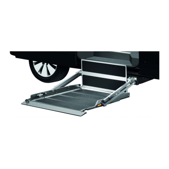
Layout and Function Hydraulic aggregate Transfer plate Carrier arms Cassette Carrier arms Platform Roll-off guard Figure 1: Cassette Lifts K70 and K90 Page 14 of 92 Cassette Lift K70 / K90 / K90 ACTIVE... -
Page 15: Platform
Cassette Lift K90 ACTIVE 2.1.1 Platform The platforms on the Cassette Lifts K70, K90 and K90 ACTIVE are of differing design: With the K70 and K90, the wheelchair is pushed onto the platform in the direction of the door of the vehicle, below which the Cassette Lift is installed (see Figure 3). - Page 16 (see Figure 5 and Figure 6, page 17). Transfer plate Figure 5 Cassette Lifts K70 and K90, Interior Floor Level Page 16 of 92 Cassette Lift K70 / K90 / K90 ACTIVE...
- Page 17 (see Figure 5, page 16, and Figure 6). On the K70 and K90, one of the platform’s two side guards is option- ally shortened to extend roughly half way along that side. This pro-...
-
Page 18: Mechanics And Hydraulics With Carrier Arms
The transfer plate automatically folds down when the platform is retracted. On the K70 and K90 there are two carrier arms on both the left- and right-hand sides of the platform (see Figure 10). Transfer plate... -
Page 19: Cassette
(see Figure 12, page 20, and Figure 13, page 20). The cassette also con- tains the carrier frame to which the internal carriage and carrier arms are attached. Cassette Lift K70 / K90 / K90 ACTIVE Page 19 of 92... - Page 20 Roll-off guard Figure 12 Cassette K70 and K90 Hydraulic aggregate Manually-operated pump (optional) Cassette Platform side guard Operating lever for the manually-operated pump Figure 13 Cassette K90 ACTIVE Page 20 of 92 Cassette Lift K70 / K90 / K90 ACTIVE...
-
Page 21: Rating Plate
Rating Plate A rating plate, which contains the fundamental data, is attached to the Cassette Lift (see Figure 14). The rating plate on the K70 and K90 is located on the right-hand side of the platform. The rating plate on the K90 ACTIVE is located on the strut of the internal carriage, behind the transfer plate. -
Page 22: Bluetooth Remote Control (Optional Extra)
An optional Bluetooth remote control, that can replicate all of the ca- ble-connected remote control functions, is available for the Cassette Lift (see Figure 16). Cover USB connection Figure 16 Bluetooth Remote Control, Operating Controls Page 22 of 92 Cassette Lift K70 / K90 / K90 ACTIVE... - Page 23 Activates the button lighting in ad- verse lighting conditions. "Bluetooth" LED Blinks once per second when the connection to the receiver has been established. Colour of the LED: green Cassette Lift K70 / K90 / K90 ACTIVE Page 23 of 92...
-
Page 24: Remote Control Per Smartphone App
An optional Smartphone App, that can replicate all of the cable-con- nected or Bluetooth remote control functions, is available for the Cas- sette Lift with Bluetooth remote control (see Figure 17, page 25). Page 24 of 92 Cassette Lift K70 / K90 / K90 ACTIVE... - Page 25 Brings the platform to the position button from which it can be retracted into the cassette. The platform must be higher than the cassette for this button to be effective. No function. Cassette Lift K70 / K90 / K90 ACTIVE Page 25 of 92...
-
Page 26: Technical Data
Safeguard against ex- Pressure control valve 190 bar cess hydraulic pressure Rated current 34 A Electrical rating 0.5 kW Hydraulic tank capacity approx. 1 l Page 26 of 92 Cassette Lift K70 / K90 / K90 ACTIVE... -
Page 27: Transportation
Remember that a Cassette Lift weighs up to 200 kg (K90). Never stand under suspended loads. NOTE The AMF-Bruns GmbH will accept no liability whatsoever for damage or injury caused by incorrect transportation. Cassette Lift K70 / K90 / K90 ACTIVE... -
Page 28: Installation / Commissioning
Installation / Commissioning 4 Installation / Commissioning The Cassette Lift must be installed in accordance with the AMF-Bruns Installation Instructions applicable to the vehicle in question. DANGER! Danger through incorrect installation. A number of risks of personal injury and material damage can be caused if the cassette lift is incorrectly installed in the vehicle. -
Page 29: Operation
“Retract” button (Position 1, Figure 16, page 22) on the Bluetooth re- mote control for more than five seconds. NOTE The control system on the K70 and K90 Cassette Lifts has an inte- grated “play-protect” facility that temporarily inhibits operation under the following conditions:... -
Page 30: Safety Regulations For Operation
Cassette Lift. If you no longer use the Cassette Lift or if you want to leave the vehicle, close all doors and lock the vehicle. Page 30 of 92 Cassette Lift K70 / K90 / K90 ACTIVE... - Page 31 Always stand at an adequately safe distance from the platform during operation. Inform other persons of the danger. Stop the Cassette Lift if any persons enter the danger zone. Cassette Lift K70 / K90 / K90 ACTIVE Page 31 of 92...
-
Page 32: Embarkation Procedure
Take an accompanying person along if there is a risk that the Cas- sette Lift can ice up. Embarkation Procedure Switch the vehicle's engine OFF. Remove the ignition key. Apply the vehicle's handbrake. Page 32 of 92 Cassette Lift K70 / K90 / K90 ACTIVE... - Page 33 (see Figure 18, page 34). Therefore: Keep a safe distance from the platform when it is lowering. If necessary, inform other persons of the danger. Stop the Cassette Lift if necessary. Cassette Lift K70 / K90 / K90 ACTIVE Page 33 of 92...
- Page 34 Make certain that the passenger’s feet do not inadvertently get caught between the carrier arms or between carrier arms and plat- form. Page 34 of 92 Cassette Lift K70 / K90 / K90 ACTIVE...
- Page 35 Push the wheelchair into the vehicle. Take hold of the cable-connected remote control, Bluetooth re- mote control or Smartphone wit App installed. Lower the platform to the retract position. Cassette Lift K70 / K90 / K90 ACTIVE Page 35 of 92...
-
Page 36: Disembarkation Procedure
Take hold of the cable-connected remote control, Bluetooth re- mote control or Smartphone with remote control App installed. Make certain that there are no persons within the range of move- ment of the platform. Page 36 of 92 Cassette Lift K70 / K90 / K90 ACTIVE... - Page 37 For commercial or communal use: Make sure that the passenger remains calm. Talk to the passenger to keep him / her calm. Stop the platform if necessary. Cassette Lift K70 / K90 / K90 ACTIVE Page 37 of 92...
- Page 38 Once again take hold of the cable-connected remote control, Bluetooth remote control or your Smartphone. Raise the platform until it reaches its highest position. Lower the platform to the retract position. Page 38 of 92 Cassette Lift K70 / K90 / K90 ACTIVE...
-
Page 39: Vehicle Fuel Gauge (K70 And K90 Only)
NOTE During installation of the Cassette Lift, the original fuel tank may have been replaced by a special fuel tank from AMF-Bruns or the position of the original fuel tank may have been changed. A precise indication of the fuel level may no longer be possible. -
Page 40: Teaching The Bluetooth Remote Control In
Press and hold the "Retract" button (1) for at least one second until the "State of Charge" LED (9) lights continuously and the "Blue- tooth" LED (8) blinks. Page 40 of 92 Cassette Lift K70 / K90 / K90 ACTIVE... -
Page 41: Installing The Remote Control App And Teaching It In
Bluetooth receiver on the cassette lift. Connection to the receiver is set up via the Bluetooth Low Energy Standard. Observe the system requirements for your Smartphone given in this section. Cassette Lift K70 / K90 / K90 ACTIVE Page 41 of 92... - Page 42 In order to switch the Bluetooth receiver ON once again when the Cassette Lift is switched ON, press the “Retract” button (Position 1, Figure 15, page 21) on the cable-connected remote control. Page 42 of 92 Cassette Lift K70 / K90 / K90 ACTIVE...
-
Page 43: Emergency Mode
Extending the platform from the cassette On the opposite side of the vehicle to the platform there is a plug in the cassette housing (see Figure 23). Figure 23 Plug Cassette Lift K70 / K90 / K90 ACTIVE Page 43 of 92... - Page 44 Remove the hook from the opening. Fully extend the platform. If the platform does not extend: Pull the platform approx. 10 to 15 cm out of the cassette manually (2nd person). Page 44 of 92 Cassette Lift K70 / K90 / K90 ACTIVE...
-
Page 45: Raising The Platform
Figure 26 Inserting the Pump Operating Lever Raise the platform by pumping the pump operating lever (see Fig- ure 27). Figure 27 Raising the Platform Cassette Lift K70 / K90 / K90 ACTIVE Page 45 of 92... -
Page 46: Lowering The Platform
Cassette Figure 28 Lowering the Platform in the Emergency Mode The platform lowers. Close the ball-cock as soon as the platform has lowered to the desired height. Page 46 of 92 Cassette Lift K70 / K90 / K90 ACTIVE... -
Page 47: Retracting The Platform Into The Cassette
6-pole connector to the cas- connector sette lift (hydraulic aggregate) Figure 29 Control Unit and Connections for K70 / K90 (1) Figure 30 Control Unit and Connections for K70 / K90 (2) Manually push the platform fully into the cassette. -
Page 48: Emergency Operation K90 Active
Emergency Mode Only K70: Pull the latch once the platform has initially latched (see Figure 25, page 44). Only push the platform fully into the cassette when this has been done. If the platform does not latch in position in the cassette, secure it against sliding out of the cassette using wire or other suitable ma- terials. -
Page 49: Raising The Platform
Interrupt the lowering procedure if necessary. Open the ball-cock by turning the lever to the left (see Figure 33). Ball-cock Lever Figure 33 Opening the Ball-Cock The platform lowers. Cassette Lift K70 / K90 / K90 ACTIVE Page 49 of 92... -
Page 50: Retracting The Platform Into The Cassette
Remove the relay cover (see Figure 35 and Figure 36). Relay Cover Figure 35 Relay Cover Relay Cover Figure 36 Removing the Relay Cover Pull one of the two changeover relays out (see Figure 37). Page 50 of 92 Cassette Lift K70 / K90 / K90 ACTIVE... - Page 51 Press firmly in order to unlatch the platform. Figure 39 Releasing the Latch Releasing the latch releases the platform. Manually push the platform approx. 2 cm into the cassette. Cassette Lift K70 / K90 / K90 ACTIVE Page 51 of 92...
-
Page 52: Maintenance And Repair
Always refit protective and safety devices if they have been re- moved (e. g. for maintenance or repair purposes). Never modify, bypass or remove protective and safety devices. Page 52 of 92 Cassette Lift K70 / K90 / K90 ACTIVE... -
Page 53: Routine Maintenance Work
Initiate repairs if necessary. Inspect the state of wear and stability of the rubbing protector in the vehicle on which the transfer plate rests when raising and lowering the platform. Cassette Lift K70 / K90 / K90 ACTIVE Page 53 of 92... -
Page 54: Maintenance Records
Cassette Lift is not retracted (stowed). The warning signal and blinkers must only go off when the platform is fully retracted once again. Initiate repairs if the warning signal or the blinkers do not function correctly. Page 54 of 92 Cassette Lift K70 / K90 / K90 ACTIVE... -
Page 55: Door Contact Switch
For detailed information regarding the yearly inspection of the Cas- sette Lift by a technical expert: see Chapter 11, "Inspection Log", page 70. Cassette Lift K70 / K90 / K90 ACTIVE Page 55 of 92... -
Page 56: Maintenance And Repair Record
Maintenance and Repair Maintenance and Repair Record Maintenance Work Carried Out Date Signature Remarks / Work Done Page 56 of 92 Cassette Lift K70 / K90 / K90 ACTIVE... -
Page 57: Commissioning And Conservation
When the Cassette Lift's useful life has expired, it must only be dis- posed of by qualified specialists. The manufacturer will accept no lia- bility for damage caused by incorrect disposal. Cassette Lift K70 / K90 / K90 ACTIVE Page 57 of 92... -
Page 58: Faults And Troubleshooting
Smartphone App if necessary (see Section 5.6, page 41). The Bluetooth control box is Contact the customer service depart- not installed. ment (see Chapter 14, page 90). Page 58 of 92 Cassette Lift K70 / K90 / K90 ACTIVE... - Page 59 (see tive. Section 6.1, page 43 (K70 / K90) or Sec- tion 6.2, page 48 (K90 ACTIVE)) and do not use it again. Contact a specialist workshop. The platform does not ex-...
- Page 60 Bluetooth remote emergency operating mode (see Sec- ground. control or Smartphone App is tion 6.1, page 43 (K70 / K90) or Sec- defective or the contactor has tion 6.2, page 48 (K90 ACTIVE)). tripped. Have the remote control and contactor checked in a specialist workshop.
- Page 61 The ball-cock is open. Close the ball-cock (see Figure 28, page 46 (K70 / K90), or Figure 34, page 50 (K90 ACTIVE)). Cassette Lift K70 / K90 / K90 ACTIVE Page 61 of 92...
-
Page 62: Into The Cassette (K70 / K90)
Rollers Figure 41 Rollers (K90) A guide rail is fitted to each side of the inside the cassette (see Figure 42, page 63, and Figure 43, page 63). Page 62 of 92 Cassette Lift K70 / K90 / K90 ACTIVE... - Page 63 If in doubt, a specialist workshop must decide whether the retract position or the rollers need to be re-adjusted (adjusting the rollers: see Section 10.1.2, page 66). Cassette Lift K70 / K90 / K90 ACTIVE Page 63 of 92...
-
Page 64: Tion (K70 / K90)
Cassette Lift is no longer operational. Figure 44 Adjusting the Switching Cam, View from Above (K70) Page 64 of 92 Cassette Lift K70 / K90 / K90 ACTIVE... - Page 65 (e.g. of wood or aluminium) between the hammer and switching cam. Figure 46 Adjusting the Switching Cam, View from Below (K70) Cassette Lift K70 / K90 / K90 ACTIVE Page 65 of 92...
-
Page 66: Adjusting The Rollers (K70 / K90)
Carry out a trial run. Repeat the procedure if the roller still hits the leading edge of the guide rail when the platform is being retracted into the cassette. Page 66 of 92 Cassette Lift K70 / K90 / K90 ACTIVE... -
Page 67: Adjusting The Switching Point For The Retract Position
Do not loosen the switching cam’s securing screw. If the cam’s se- curing screw is loosened, the switching cam must be completely re- adjusted and the Cassette Lift is no longer operational. Cassette Lift K70 / K90 / K90 ACTIVE Page 67 of 92... - Page 68 Figure 51: Adjusting the Switching Cam for the Retract Position (2) Carry out a trial run. Repeat the procedure if the platform is still too high when being retracted. Page 68 of 92 Cassette Lift K70 / K90 / K90 ACTIVE...
-
Page 69: Charging The Bluetooth Remote Control Battery
Disconnect the charging cable from the USB connection on the remote control. Fit the cover to the USB connection. Stow the charging cable and charger away. Cassette Lift K70 / K90 / K90 ACTIVE Page 69 of 92... -
Page 70: Inspection Log
European Union or Turkey or other signatory states of the Agreement of the European Economic Area) that they are able to assess the safe working condition of such lifting platforms (from: BGR 500). Page 70 of 92 Cassette Lift K70 / K90 / K90 ACTIVE... -
Page 71: Inspection Log Master Data Sheet
11.1 Inspection Log Master Data Sheet Cassette Lift Master Data Sheet Serial No./Type* ………………………………….…………………………………………………………………………….. Number plate .……………………………………………………………………………………………………………….. Owner ..…………………………………………………………………………………………………………….. .……………………………………………………………………………………………………………….. .……………………………………………………………………………………………………………….. Year built .……………………………………………………………………………………………………………….. Commissioned on .……………………………………………………………………………………………………………….. * see rating plate Cassette Lift K70 / K90 / K90 ACTIVE Page 71 of 92... -
Page 72: Inspection List
Electrical drive for the roll-off guard (K70) Functional check Electrical cables Inspection of the connections in accordance with the electrical circuit diagram Inspection of the cables for damage to the insula- tion Page 72 of 92 Cassette Lift K70 / K90 / K90 ACTIVE... -
Page 73: Inspection Results
….…………………………………………………………………………………………………… Number plate ………………………………………………………………………………………………………. Installation has been carried out correctly! Place, date ………………………………………………………………………………………………………. ………………………………………………………………..…. ………………………………………………………………..…. Installation company / Company stamp Technical expert / Signature * see rating plate Cassette Lift K70 / K90 / K90 ACTIVE Page 73 of 92... - Page 74 Note has been taken of the result of the inspection. All deficiencies have been rectified. Confirmation by the owner or his representative with date and signature ……………………………………………………………………..…. ……………………………………………………………………..…. Place / date Signature (owner) * see rating plate Page 74 of 92 Cassette Lift K70 / K90 / K90 ACTIVE...
- Page 75 Note has been taken of the result of the inspection. All deficiencies have been rectified. Confirmation by the owner or his representative with date and signature ……………………………………………………………………..…. ……………………………………………………………………..…. Place / date Signature (owner) * see rating plate Cassette Lift K70 / K90 / K90 ACTIVE Page 75 of 92...
- Page 76 Note has been taken of the result of the inspection. All deficiencies have been rectified. Confirmation by the owner or his representative with date and signature ……………………………………………………………………..…. ……………………………………………………………………..…. Place / date Signature (owner) * see rating plate Page 76 of 92 Cassette Lift K70 / K90 / K90 ACTIVE...
- Page 77 Note has been taken of the result of the inspection. All deficiencies have been rectified. Confirmation by the owner or his representative with date and signature ……………………………………………………………………..…. ……………………………………………………………………..…. Place / date Signature (owner) * see rating plate Cassette Lift K70 / K90 / K90 ACTIVE Page 77 of 92...
- Page 78 Note has been taken of the result of the inspection. All deficiencies have been rectified. Confirmation by the owner or his representative with date and signature ……………………………………………………………………..…. ……………………………………………………………………..…. Place / date Signature (owner) * see rating plate Page 78 of 92 Cassette Lift K70 / K90 / K90 ACTIVE...
- Page 79 Note has been taken of the result of the inspection. All deficiencies have been rectified. Confirmation by the owner or his representative with date and signature ……………………………………………………………………..…. ……………………………………………………………………..…. Place / date Signature (owner) * see rating plate Cassette Lift K70 / K90 / K90 ACTIVE Page 79 of 92...
- Page 80 Note has been taken of the result of the inspection. All deficiencies have been rectified. Confirmation by the owner or his representative with date and signature ……………………………………………………………………..…. ……………………………………………………………………..…. Place / date Signature (owner) * see rating plate Page 80 of 92 Cassette Lift K70 / K90 / K90 ACTIVE...
- Page 81 Note has been taken of the result of the inspection. All deficiencies have been rectified. Confirmation by the owner or his representative with date and signature ……………………………………………………………………..…. ……………………………………………………………………..…. Place / date Signature (owner) * see rating plate Cassette Lift K70 / K90 / K90 ACTIVE Page 81 of 92...
-
Page 82: Electrical Circuit Diagrams
PIN 4 cable 11 Door contact switch 12-pole connector from the cassette lift (front view) Vehicle floor Figure 52: Electrical Connection Diagram K70 / K90 12.2 Electrical Connection Diagram K90A (with/without optional Bluetooth remote control) Connector for the hand- held remote control... -
Page 83: Electrical Circuit Diagram K70 / K90
Only for K70, otherwise straight through cable Fl. connect. housing, 2-pole Battery Cassette lowering contac- valve Pressure switch Pump Internal carriage Platform Figure 54: Electrical Circuit Diagram K70 / K90 Cassette Lift K70 / K90 / K90 ACTIVE Page 83 of 92... - Page 84 S10 (normally open) Switch for end position and solenoid YE-BK yellow-black S11 (normally closed) Door contact switch YE-WH yellow-white Buzzer in the vehicle Buzzer on the internal carriage Page 84 of 92 Cassette Lift K70 / K90 / K90 ACTIVE...
-
Page 85: Electrical Circuit Diagram K90 Active
Electrical Circuit Diagrams 12.4 Electrical Circuit Diagram K90 ACTIVE Blinker BN 1.5 mm² connected to No. 8 at a connection point Figure 55 Electrical Circuit Diagram K90 ACTIVE Cassette Lift K70 / K90 / K90 ACTIVE Page 85 of 92... - Page 86 S1 - S4 Switch Door contact switch Turquoise Retract / Extend Violet Raise / Lower White Lowering valve Yellow Solenoid Blinker transmitter Contactor Extend Retract Control System to the battery Page 86 of 92 Cassette Lift K70 / K90 / K90 ACTIVE...
-
Page 87: Hydraulic Line Diagrams
190 bar 0.35 kW 12 V Ball-cock Hand-operated pump V = 2 cm³ / stroke Hydraulic cylinder Hydraulic cylinder Hydraulic cylinder Figure 56: Hydraulic Circuit Diagram K70 Cassette Lift K70 / K90 / K90 ACTIVE Page 87 of 92... -
Page 88: Hydraulic Circuit Diagram K90
Hydraulic aggregate set to 190 bar 0.35 kW 12 V Ball-cock Hand-operated pump V = 2 cm³ / stroke Hydraulic cylinder Hydraulic cylinder Figure 57: Hydraulic Circuit Diagram K90 Page 88 of 92 Cassette Lift K70 / K90 / K90 ACTIVE... -
Page 89: Hydraulic Circuit Diagram K90 Active
Hydraulic Line Diagrams 13.3 Hydraulic Circuit Diagram K90 ACTIVE Figure 58: Hydraulic Circuit Diagram K90 ACTIVE Cassette Lift K70 / K90 / K90 ACTIVE Page 89 of 92... -
Page 90: Customer Service
NOTE Guarantee work on the cassette lift must only be carried out with the prior agreement of AMF-Bruns GmbH & Co. KG. The costs of such work will not be accepted by AMF-Bruns without prior agreement. Page 90 of 92... -
Page 91: Declaration Of Conformity
EC Machinery Directive 2006/42/EC. This declaration is rendered null and void if unauthorised modifications are made to the machine. Designation Cassette Lift Type: K70, K90, K90 ACTIVE Manufacturer: Company: AMF-Bruns GmbH & Co. KG Address: Hauptstraße 101... - Page 92 AMF-Bruns GmbH & Co. KG | Hauptstraße 101 | D-26689 Apen Telephone +49 (0) 44 89 / 72 72 22 | Fax +49 (0) 44 89 / 62 45 service.hubmatik@amf-bruns.de www.amf- bruns...
Need help?
Do you have a question about the K70 and is the answer not in the manual?
Questions and answers