Table of Contents
Advertisement
Advertisement
Table of Contents

Related Manuals for AMF-BRUNS AL1


Summary of Contents for AMF-BRUNS AL1
- Page 1 Operating Instructions LINEAR LIFT AL1 www.amf-bruns.de...
-
Page 3: Foreword
Contact our customer service department to order spare parts or accessories. The spare parts catalogue can be found in the service section of our Internet site (see Chap- ter 14, page 74). Linear Lift AL1 Page 3 of 76... - Page 4 ...gives a reference to important information in other sec- tions and documents. Some texts serve a particular purpose. These are identified as follows: Lists Instructional text, e.g. a sequence of activities. Page 4 of 76 Linear Lift AL1...
-
Page 5: Table Of Contents
5.2 Switching OFF in an Emergency (Emergency Stop) ..........26 5.3 Switching the Linear Lift ON ....... 26 5.4 Switching the Linear Lift OFF ......27 5.5 Lowering the Platform ........27 5.6 Raising the Platform ........... 30 Linear Lift AL1 Page 5 of 76... - Page 6 11.2 Inspection List ............ 62 11.3 Inspection Results ..........63 12 Electrical Circuit Diagrams ....... 71 13 Hydraulic Circuit Diagram ........ 73 14 Customer Service ..........74 15 Declaration of Conformity ....... 75 Page 6 of 76 Linear Lift AL1...
-
Page 7: Safety
Unless of course the person in the wheelchair is also the driver of the vehicle. Proper use also includes strictly adhering to the infor- mation given in these Operating Instructions. Linear Lift AL1 Page 7 of 76... -
Page 8: Improper Use
ON and OFF and who are in a position to adapt themselves to the par- ticular behaviour and needs of disabled persons. Page 8 of 76 Linear Lift AL1... -
Page 9: Product Monitoring
Guarantee work on the Linear Lift must only be carried out with the prior agreement of AMF-Bruns GmbH & Co. KG. The costs of such work will not be accepted by AMF-Bruns without prior agreement. If damage occurs, AMF-Bruns GmbH & Co. KG will require the serial number, the year built as well as a description of the damage and if possible, a photograph of the damage. -
Page 10: Safety Devices
(Proper use: see Sec- tion 1.1, page 7). The owner is responsible for ensuring that proper use is adhered to, in particular that the Linear Lift is only oper- ated by authorised persons. Page 10 of 76 Linear Lift AL1... - Page 11 The Linear Lift must not be operated in a faulty condi- tion, as serious injuries may be caused by this. If faults occur, do not use the Linear Lift until repairs have been effected. Linear Lift AL1 Page 11 of 76...
-
Page 12: Disposal
Disposal When the Linear Lift's useful life has expired, it must only be disposed of by qualified specialists. The manufacturer will accept no liability for damage caused by incorrect dis- posal. Page 12 of 76 Linear Lift AL1... -
Page 13: Description
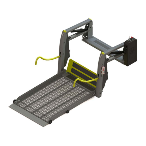
Layout and Function Carrier arms Blinkers (optional) Carrier struts Switch box with hydraulic pump Guardrails Remote control Transfer plate Roll-off guard Platform Side roll-off guards Figure 1: Linear Lift AL1 Solid, Overview Linear Lift AL1 Page 13 of 76... -
Page 14: Platform
Figure 2: Linear Lift AL1 Solid, Embarkation and Disembarkation Level The Linear Lift AL1 Solid has a one-piece platform. The platform of the Linear Lift AL1 Panorama is made up of two sections such that it is shortened when folded up to the stowed position. - Page 15 Lift is installed in the vehicle can not be seen from the out- side (see Figure 3 and Figure 4). Platform Figure 3: Linear Lift AL1 Panorama, Overview Platform Figure 4: Linear Lift AL1 Panorama, Stowed Position Linear Lift AL1 Page 15 of 76...
-
Page 16: Transfer Plate
Description The platform of the Linear Lift AL1 Split is split lengthwise. When it is stowed in the driving position, the two halves of the platform separate (see Figure 5). Because of this, it is possible to enter and leave the vehicle by way of the door in which the Linear Lift is installed, even though the Linear Lift is in the vertical, stowed position. -
Page 17: Lifting Unit
Figure 1, page 13). The operating voltage for the motor is supplied by the starter battery. The hydraulic cylinders that are powered by the pump are located between the carrier arms. The hydraulic system can be manually operated in an emergency. Linear Lift AL1 Page 17 of 76... -
Page 18: Rating Plate
A rating plate, which contains the fundamental data, is at- tached to the Linear Lift (see Figure 6). The rating plate is located on the floor anchorage. Year of manufacture Designation Version Load bearing Serial number capability Manufacturer Figure 6: Rating Plate Page 18 of 76 Linear Lift AL1... -
Page 19: Technical Data
Description 2.3 Technical Data Designation Linear Lift AL1 Type / Lifting platform Solid 1065 Solid 1130 Solid 1200 Solid 1380 Panorama 1200 Panorama 1400 Split 1085 Split 1085 S Split 1300 Weight 133 kg ± 10 Permissible operating pressure 92 bar Permissible number of persons on the max. -
Page 20: Operating Controls
Description 2.4 Operating Controls No function. Figure 7: Operating Controls on the Remote Control Figure 8: Operating Controls on the Hydraulic Pump Page 20 of 76 Linear Lift AL1... - Page 21 Raises the Linear Lift to the ver- “STOW” tical, stowed position. Battery isolation Interrupts the power supply to switch the hydraulic pump motor. Circuit breaker Trips when a fault occurs and renders the remote control inoperative. Linear Lift AL1 Page 21 of 76...
-
Page 22: Transportation
The Linear Lift can fall over during transportation. There is a risk of personal injury and material damage. Therefore: Transportation of the Linear Lift is carried out by the manufacturer or by trained, experienced personnel. Page 22 of 76 Linear Lift AL1... -
Page 23: Installation / Commissioning
Installation / Commissioning Installation / Commissioning The Linear Lift must be installed in accordance with the AMF-Bruns Installation Instructions applicable to the vehi- cle in question. DANGER! Risk of injury through incorrect installation. A number of risks of personal injury and material damage can be caused if the Linear Lift is incorrectly installed in the vehicle. -
Page 24: Operation
Before driving off: Switch the Linear Lift OFF at the mas- ter switch. Before leaving the vehicle: Remove the ignition key, bring the Linear Lift to the stowed position, switch the Linear Lift OFF and lock the vehicle’s doors. Page 24 of 76 Linear Lift AL1... - Page 25 Therefore: never modify, bypass or remove protective and safety devices. Always refit protective and safety devices if they have been removed (e. g. for maintenance or repair pur- poses). Linear Lift AL1 Page 25 of 76...
-
Page 26: Switching Off In An Emergency
When operating the Linear Lift, make certain that the door can not swing closed due to wind or other influ- ences. Insert the key into the battery isolation switch (5) (see Figure 9, page 26). Page 26 of 76 Linear Lift AL1... -
Page 27: Switching The Linear Lift Off
Make sure that the centre of gravity of the wheelchair is in the centre of the platform (see Figure 10). This will prevent the Linear Lift from excessive wear. Linear Lift AL1 Page 27 of 76... - Page 28 Stop the platform if necessary. Make sure that the passenger does not reach into the carrier arms. Remove the remote control from its holder on the side of the lifting unit. Page 28 of 76 Linear Lift AL1...
- Page 29 If necessary, stop the Linear Lift. Right Wrong Figure 11: Risk of Injury When Lowering the Platform. Release the “DOWN” push-button (2) on the remote control. Replace the remote control to its holder. Linear Lift AL1 Page 29 of 76...
-
Page 30: Raising The Platform
Make sure that the passenger remains calm. Talk to the passenger to keep him / her calm. Make sure that the passenger does not reach into the carrier arms. Page 30 of 76 Linear Lift AL1... - Page 31 The arrester hooks serve only as an emergency measure, to prevent the Lift from falling against the door of the vehi- cle if there is a loss of pressure in the hydraulic system (see Section 10.6, page 54). Linear Lift AL1 Page 31 of 76...
- Page 32 Linear Lift up. Replace the remote control to its holder. Switch the Linear Lift OFF at the battery isolation switch (5) (see Figure 9, page 26). Close the rear vehicle door. Page 32 of 76 Linear Lift AL1...
-
Page 33: Emergency Mode
Pull the operating lever out of its stowage clips on the floor anchorage (see Figure 13). Operating lever Stowage clips Figure 13: Removing the Operating Lever Insert the operating lever into the pump actuator on the hydraulic system (see Figure 14). Linear Lift AL1 Page 33 of 76... - Page 34 It takes approx. 15-20 strokes before the platform starts moving. Figure 15: Pump Actuator (2) Remove the operating lever from the pump actuator. Replace the operating lever to its stowage clips. Page 34 of 76 Linear Lift AL1...
-
Page 35: Lowering In The Emergency Mode
Figure 16: Emergency Lowering Valve (1) Open the emergency lowering valve by turning the lever slowly in an anti-clockwise direction (see Figure 17). Figure 17: Emergency Lowering Valve (2) The platform lowers. Linear Lift AL1 Page 35 of 76... - Page 36 Remove the lever from the emergency lowering valve. Replace the operating lever to its stowage clips. Page 36 of 76 Linear Lift AL1...
-
Page 37: Maintenance And Repair
Therefore: Do not remove springs if they are under tension. Do not take gas pressure springs apart. They are under high pressure. Linear Lift AL1 Page 37 of 76... -
Page 38: Routine Maintenance Work
Linear Lift. Initiate repairs if necessary. weekly Inspect the contact points of the torsion springs 100° on the shaft of the platform for wear and sufficient lu- brication (grease). Apply grease if necessary. Page 38 of 76 Linear Lift AL1... -
Page 39: Maintenance Record
7.4 Inspection of the Hydraulic Hoses. The inspection of hydraulic hoses extends to: Seating of the fastenings Damage Ageing Brittleness Porosity If damage is found, have the hydraulic hoses replaced. Linear Lift AL1 Page 39 of 76... -
Page 40: Yearly Inspection
For detailed information regarding the yearly inspection of the Linear Lift by a technical expert: see Chapter 11, "In- spection Log", page 60. 7.6 Maintenance and Inspection Record Maintenance work carried out Date Signature Remarks / work carried out Page 40 of 76 Linear Lift AL1... -
Page 41: De-Commissioning And Conservation
De-Commissioning and Conservation 8 De-Commissioning and Conserva- tion For queries regarding de-commissioning and conservation, contact our customer services department (see Chapter 14, page 74). Linear Lift AL1 Page 41 of 76... -
Page 42: Faults And Troubleshooting
The Linear Lift folds out The starter switch is defective. Check the starter switch and and lowers but does replace if necessary. not raise. The emergency lowering valve Shut the emergency lowering is open. valve. Page 42 of 76 Linear Lift AL1... - Page 43 The platform segments are not Finely adjust the platform platform do not rest adjusted correctly. segments to one another (see completely on the Section 10.3, page 48). ground when the lift is lowered to the ground. Linear Lift AL1 Page 43 of 76...
- Page 44 (see Section 10.4, page 49). lifting unit in the stowed posi- tion. The micro-switch on the oppo- Finely adjust the micro-switch site side to the hydraulic ag- (see Section 10.7, page 55). gregate requires adjustment. Page 44 of 76 Linear Lift AL1...
-
Page 45: Fine Adjustments
When the platform has been fully lowered, the roll-off guard must fold down to the ground. The edge of the roll- off guard must be in contact with the ground (see Figure 18). Figure 18: Roll-Off Guard Folded Down Linear Lift AL1 Page 45 of 76... - Page 46 Check the gap between the edge of the roll-off guard and the ground. Repeat the adjustment procedure, until the platform has the correct angle of tilt and the roll-off guard rests cleanly on the ground. Page 46 of 76 Linear Lift AL1...
-
Page 47: Transfer Plate
Tighten the locking nut once again. Lower the platform slightly, and then raise it to the embarkation / disembarkation level again (see Figure 2, page 14). Repeat the adjustment procedure if necessary. Linear Lift AL1 Page 47 of 76... -
Page 48: Split Platform: Adjusting The Platform
Turn the bolts in an anti-clockwise direction to raise the platform segments. Tighten the locking nuts once again. Hold the hexagonal section of the bolt firmly when doing so. Page 48 of 76 Linear Lift AL1... -
Page 49: Elbow Joints
Loosen the locking nuts on the top and bottom connection eyes connecting tubes (see Figure 23 and Figure 24, page 50). NOTE The bottom connection eye locking nuts have left-hand threads and the top connecting eye locking nuts have tight-hand threads. Linear Lift AL1 Page 49 of 76... - Page 50 Tighten the locking nuts once again. Run the platform to the vertical, stowed position. Check that the stoppers rest snugly against the lifting unit (see Figure 22, page 49). Repeat the adjustment procedure if necessary. Page 50 of 76 Linear Lift AL1...
-
Page 51: Adjusting The Panorama Platform
Loosen the locking nuts on the cable linkages on both sides (see Figure 26). Cable linkage Figure 26: Loosening the Locking Nut Linear Lift AL1 Page 51 of 76... - Page 52 (see Figure 28). The platform segments must be exactly parallel to one another (see Figure 29, page 53). Adjuster screw Figure 27: Adjusting the Cable Linkages Chocks Figure 28: Chocks Page 52 of 76 Linear Lift AL1...
- Page 53 Fine Adjustments Upper platform segment Bottom platform segment Figure 29: Parallelism Linear Lift AL1 Page 53 of 76...
-
Page 54: Arrester Hooks
Run the platform to the stowed position. Adjust the eccentrics as shown in Figure 30. By doing this, the Linear Lift has the least possible range of movement before the arrester hooks engage. Page 54 of 76 Linear Lift AL1... -
Page 55: Micro-Switches
Micro-switch 2 Micro-switch 1 Abrasion protector Figure 32: Aggregate Side Micro-Switches The two micro-switches on the aggregate side stop the platform at the embarkation / disembarkation level when it is being raised or lowered. Linear Lift AL1 Page 55 of 76... - Page 56 Lower the platform again by pressing the “DOWN” (2) push-button, until the abrasion protector on the elbow joint is no longer in contact with the carrier arm. Loosen the three micro-switch fastening screws (see Figure 33). Page 56 of 76 Linear Lift AL1...
- Page 57 Repeat the adjustment if the platform is not exactly hori- zontal. Fully lower the platform by pressing the “DEPLOY” (3) and “DOWN” (2) push-buttons. Press and hold the “UP” push-button (1). Linear Lift AL1 Page 57 of 76...
- Page 58 / disembarkation level. Check once again that the abrasion protectors on both elbow joints are firmly in contact with the carrier arms. If this is not the case, repeat the adjustment procedure. Page 58 of 76 Linear Lift AL1...
- Page 59 When doing so, make sure that the micro-switch pro- trudes sufficiently from the carrier arm. If not, the abra- sion protector will not actuate it. Carry out the above checks once again. If necessary, re-adjust the micro-switch. Linear Lift AL1 Page 59 of 76...
-
Page 60: Inspection Log
European Union or Turkey or other signatory states of the Agreement of the European Economic Area) that they are able to assess the safe working condition of such lifting platforms (from: BGR 500). Page 60 of 76 Linear Lift AL1... -
Page 61: Inspection Log Master Data Sheet
Inspection Log 11.1 Inspection Log Master Data Sheet Linear Lift Master Data Sheet Serial No. /Type* …………………………………………………………………………………………………. Number plate …………………………………………………………………………………………………. Owner …………………………………………………………………………………………………. …………………………………………………………………………………………………. …………………………………………………………………………………………………. Year built: …………………………………………………………………………………………………. Commissioned on …………………………………………………………………………………………………. * see rating plate Linear Lift AL1 Page 61 of 76... -
Page 62: Inspection List
Push-buttons on the remote control Functional check Battery isolation switch Functional check Electrical cables Inspection of the connections in accordance with the electrical circuit diagram Inspection of the cables for damage to the insulation Page 62 of 76 Linear Lift AL1... -
Page 63: Inspection Results
Installation inspection for ………………………………………………………………………………………… Serial No. /Type* …..……………………………………………………………………………………. Number plate …………………………..……………………………………………………………. Installation has been carried out correctly! Place, date ……………………………………………………………………..…. ……………………………………………………………………..…. Installation company / Company stamp Technical expert / Signature * see rating plate Linear Lift AL1 Page 63 of 76... - Page 64 Note has been taken of the result of the inspection. All deficiencies have been rectified. Confirmation by the owner or his representative with date and signature ……………………………………………………………………..…. ……………………………………………………………………..…. Place / date Signature (owner) * see rating plate Page 64 of 76 Linear Lift AL1...
- Page 65 Note has been taken of the result of the inspection. All deficiencies have been rectified. Confirmation by the owner or his representative with date and signature ……………………………………………………………………..…. ……………………………………………………………………..…. Place / date Signature (owner) * see rating plate Linear Lift AL1 Page 65 of 76...
- Page 66 Note has been taken of the result of the inspection. All deficiencies have been rectified. Confirmation by the owner or his representative with date and signature ……………………………………………………………………..…. ……………………………………………………………………..…. Place / date Signature (owner) * see rating plate Page 66 of 76 Linear Lift AL1...
- Page 67 Note has been taken of the result of the inspection. All deficiencies have been rectified. Confirmation by the owner or his representative with date and signature ……………………………………………………………………..…. ……………………………………………………………………..…. Place / date Signature (owner) * see rating plate Linear Lift AL1 Page 67 of 76...
- Page 68 Note has been taken of the result of the inspection. All deficiencies have been rectified. Confirmation by the owner or his representative with date and signature ……………………………………………………………………..…. ……………………………………………………………………..…. Place / date Signature (owner) * see rating plate Page 68 of 76 Linear Lift AL1...
- Page 69 Note has been taken of the result of the inspection. All deficiencies have been rectified. Confirmation by the owner or his representative with date and signature ……………………………………………………………………..…. ……………………………………………………………………..…. Place / date Signature (owner) * see rating plate Linear Lift AL1 Page 69 of 76...
- Page 70 Note has been taken of the result of the inspection. All deficiencies have been rectified. Confirmation by the owner or his representative with date and signature ……………………………………………………………………..…. ……………………………………………………………………..…. Place / date Signature (owner) * see rating plate Page 70 of 76 Linear Lift AL1...
-
Page 71: Electrical Circuit Diagrams
Electrical Circuit Diagrams 12 Electrical Circuit Diagrams Figure 34: Electrical Circuit Diagram (12 V supply, platform lighting) Linear Lift AL1 Page 71 of 76... - Page 72 Figure 35: Electrical Circuit Diagram (position switches and manual switches) Colour Abbreviation Colour Abbreviation (acc. to IEC 60757) (acc. to IEC 60757) Black Blue Brown Violet Grey Orange White Yellow Pink Green Turquoise Page 72 of 76 Linear Lift AL1...
-
Page 73: Hydraulic Circuit Diagram
13 Hydraulic Circuit Diagram Figure 36: Hydraulic Circuit Diagram Block material Aluminium, bright p (DBV) 92 bar + 2 bar p (max) 210 bar Valve voltage U = 12 V DC Installation position vertical Linear Lift AL1 Page 73 of 76... -
Page 74: Customer Service
The costs of such work will not be accepted by AMF-Bruns without prior agreement. In case of a claim, AMF-Bruns GmbH & Co. KG will require the serial number, the year built as well as a description of the damage and if possible a photograph of the damage. -
Page 75: Declaration Of Conformity
EC Machinery Directive 2006/42/EC. This declaration is rendered null and void if unauthorised modifications are made to the machine. Designation Linear Lift Type: AL1 Solid, AL1 Panorama, AL1 Split Manufacturer: Company: AMF-Bruns GmbH & Co. KG Address: Hauptstraße 101... - Page 76 AMF-Bruns GmbH & Co. KG | Hauptstraße 101 | 26689 Apen Telephone +49 (0) 4489 / 72 72 30 | Fax +49 (0) 4489 / 62 45 service.hubmatik@amf-bruns.de www.amf-bruns.de Reg.-No. Q1 0105027...
Need help?
Do you have a question about the AL1 and is the answer not in the manual?
Questions and answers