Table of Contents
Advertisement
Quick Links
Advertisement
Table of Contents

Related Manuals for AMF-BRUNS K70


Summary of Contents for AMF-BRUNS K70
- Page 1 Operating Instructions BACK-IN-BOX LIFT K70 K90 / K90 ACTIVE www.amf-bruns.de...
-
Page 3: Foreword
Foreword Foreword Dear Reader, these Operating Instructions provide all information neces- sary to safely operate the Back-in-Box-Lifts K70, K90 and K90 ACTIVE. The Back-in-Box-Lifts are designed and constructed in ac- cordance with state of the art technology and recognised safety standards. Persons and materials can however be endangered, as not all danger areas can be eliminated if the functional capability is to be maintained. - Page 4 ...gives a reference to important information in other sec- tions and documents. Some texts serve a particular purpose. These are identified as follows: • Lists. ð Instructional text, e.g. a sequence of activities. Page 4 of 100 Back-in-Box-Lift K70 / K90 / K90 ACTIVE...
-
Page 5: Table Of Contents
5 Operation ............30 5.1 Safety Regulations for Operation ......30 5.2 Embarkation Procedure ........33 5.3 Disembarkation Procedure ........38 5.4 Refuelling the Vehicle (K70 and K90 only) ..... 41 Back-in-Box-Lift K70 / K90 / K90 ACTIVE Page 5 of 100... - Page 6 Retracted Into the Cassette (K70 / K90)....62 9.1.1 Adjusting the switching point for the retract position (K70 / K90) ......64 9.1.2 Adjusting the rollers (K70 / K90) ....67 9.2 Adjusting the Switching Point for the Retract Position (K90 ACTIVE) ......... 68 9.3 Charging the Bluetooth Remote Control Battery .
- Page 7 Control K70 (optional) .......... 87 11.2 Electrical Circuit Diagram, Bluetooth Remote Control K90 /K90A (optional) ....... 87 11.3 Electrical Circuit Diagram K70 ......88 11.4 Electrical Circuit Diagram K90......90 11.5 Electrical Circuit Diagram K90 ACTIVE ....93 12 Hydraulic Line Diagrams ........ 95 12.1 Hydraulic Circuit Diagram K70 ......
-
Page 8: Safety
By using the Back-in-Box-Lift, persons can be embarked into or disembarked from the vehicle to which it is fitted. Proper use also includes strictly adhering to the infor- mation given in these Operating Instructions. Page 8 of 100 Back-in-Box-Lift K70 / K90 / K90 ACTIVE... -
Page 9: Improper Use
• it is used for lifting and lowering persons who are not seated in a wheelchair, • it is operated by persons who do not fulfil the necessary requirements (see Section 1.3). Back-in-Box-Lift K70 / K90 / K90 ACTIVE Page 9 of 100... -
Page 10: User Requirements
Transportation, installation, commissioning, maintenance, repair, fault finding and disposal of the Back-in-Box-Lift must only be carried out by persons with the correspond- ing technical training and experience. Page 10 of 100 Back-in-Box-Lift K70 / K90 / K90 ACTIVE... -
Page 11: Product Monitoring
AMF- Bruns GmbH & Co. KG. The costs of such work will not be accepted by AMF-Bruns without prior agreement. Danger Zone The danger zone is any area on, below or within the range of movement of the platform, as well as around the drive and carrier system, in which persons are exposed to the risk of injury or damage to health. -
Page 12: Safety Devices
A door contact switch is fitted to the vehicle door, above the Back-in-Box-Lift. It disables all functions of the Back-in-Box-Lift when the door is closed. This prevents the Back-in-Box-Lift from being operated inadvertently or by unauthorised persons. Page 12 of 100 Back-in-Box-Lift K70 / K90 / K90 ACTIVE... -
Page 13: Safety And Accident Prevention Regulations
Back-in-Box-Lift is used commercially or communally. We recommend that this annual inspection is also car- ried out if the Back-in-Box-Lift is used privately. Back-in-Box-Lift K70 / K90 / K90 ACTIVE Page 13 of 100... -
Page 14: Disposal
When the Back-in-Box-Lift's useful life has expired, it must only be disposed of by qualified specialists. The manufac- turer will accept no liability for damage caused by incorrect disposal. Page 14 of 100 Back-in-Box-Lift K70 / K90 / K90 ACTIVE... -
Page 15: Description
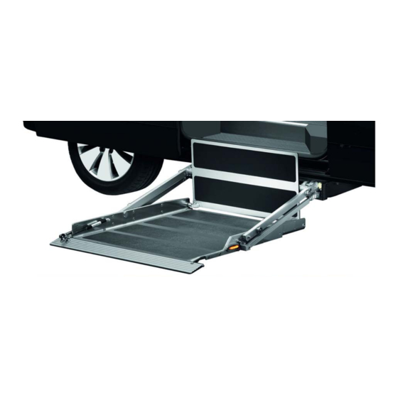
Layout and Function Hydraulic aggregate Transfer plate Carrier arms Cassette Carrier arms Platform Roll-off guard Figure 1: Back-in-Box Lifts K70 and K90 Back-in-Box-Lift K70 / K90 / K90 ACTIVE Page 15 of 100... - Page 16 Description Hydraulic aggregate Cassette Transfer plate Carrier arms Platform Roll-off guard Figure 2: Back-in-Box-Lift K90 ACTIVE Page 16 of 100 Back-in-Box-Lift K70 / K90 / K90 ACTIVE...
-
Page 17: Platform
The platforms on the Back-in-Box-Lifts K70, K90 and K90 ACTIVE are of differing design: With the K70 and K90, the wheelchair is pushed onto the platform in the direction of the door of the vehicle, below which the lift is installed (see Figure 3). - Page 18 (see Fig- ure 5 and Figure 6). Transfer plate Figure 5: Back-in-Box Lifts K70 and K90, Interior Floor Level Transfer plate Figure 6: Back-in-Box-Lift K90 ACTIVE, Interior Floor Level Guards are provided on all other sides of the platform to prevent the wheelchair from rolling off the platform (see Figure 5 and Figure 6).
- Page 19 Description On the K70 and K90, one of the platform’s two side guards is optionally shortened to extend roughly half way along that side. This provides side access to the platform, mak- ing it easier for the passenger to roll on and off the plat- form when there is limited space available outside the ve- hicle (see Figure 7).
-
Page 20: Mechanics And Hydraulics With Carrier Arms
The transfer plate automatically folds down when the platform is retracted. On the K70 and K90 there are two carrier arms on both the left- and right-hand sides of the platform (see Figure 10). -
Page 21: Cassette
22). The cassette also contains the carrier frame to which the internal carriage and carrier arms are attached. Hydraulic aggregate Manually-operated pump (optional) Cassette Operating lever for the Roll-off guard manually-operated pump Figure 12: Cassette K70 and K90 Back-in-Box-Lift K70 / K90 / K90 ACTIVE Page 21 of 100... -
Page 22: Rating Plate
A rating plate, which contains the fundamental data, is at- tached to the Back-in-Box-Lift (see Figure 14). The rating plate on the K70 and K90 is located on the right-hand side of the platform. The rating plate on the K90 ACTIVE is lo- cated on the strut of the internal carriage, behind the transfer plate. -
Page 23: Operating Controls And Indicators
Brings the platform to the button position from which it can be retracted into the cassette. The platform must be higher than the cassette for this button to be effective. No function. Back-in-Box-Lift K70 / K90 / K90 ACTIVE Page 23 of 100... -
Page 24: Bluetooth Remote Control (Optional Extra)
Brings the platform to the po- button sition from which it can be re- tracted into the cassette. The platform must be higher than the cassette for this but- ton to be effective. Page 24 of 100 Back-in-Box-Lift K70 / K90 / K90 ACTIVE... - Page 25 The Bluetooth remote control switches OFF automatically after a certain time. The Bluetooth remote control can be started again by pressing the "Retract" button (1) for long- er than three seconds. Back-in-Box-Lift K70 / K90 / K90 ACTIVE Page 25 of 100...
-
Page 26: Remote Control Per Smartphone App
Brings the platform to the button position from which it can be retracted into the cassette. The platform must be higher than the cassette for this button to be effective. No function. Page 26 of 100 Back-in-Box-Lift K70 / K90 / K90 ACTIVE... -
Page 27: Technical Data
Safeguard against ex- Pressure control valve 190 bar cess hydraulic pressure Rated current 34 A Electrical rating 0.5 kW Hydraulic tank capacity approx. 1 l Back-in-Box-Lift K70 / K90 / K90 ACTIVE Page 27 of 100... -
Page 28: Transportation
• Remember that a Back-in-Box-Lift weighs up to 200 kg (K90). • Never stand under suspended loads. NOTE The AMF-Bruns GmbH will accept no liability whatsoever for damage or injury caused by incorrect transportation. Page 28 of 100 Back-in-Box-Lift K70 / K90 / K90 ACTIVE... -
Page 29: Installation / Commissioning
Back-in-Box-Lift has been estab- lished by making a corresponding entry in the inspection log (see Chapter 10, page 73). • The Back-in-Box-Lift must not be used until this has been done. Back-in-Box-Lift K70 / K90 / K90 ACTIVE Page 29 of 100... -
Page 30: Operation
Back-in-Box-Lift. • If you no longer use the Back-in-Box-Lift or if you want to leave the vehicle, close all doors and lock the vehicle. Page 30 of 100 Back-in-Box-Lift K70 / K90 / K90 ACTIVE... - Page 31 • never modify, bypass or remove protective and safety devices. • Always refit protective and safety devices if they have been removed (e. g. for maintenance or repair purpos- es). Back-in-Box-Lift K70 / K90 / K90 ACTIVE Page 31 of 100...
- Page 32 • Only use the Back-in-Box-Lift for embarkation or dis- embarkation when this has been done. • Take an accompanying person along if there is a risk that the Back-in-Box-Lift can ice up. Page 32 of 100 Back-in-Box-Lift K70 / K90 / K90 ACTIVE...
-
Page 33: Embarkation Procedure
The transfer plate folds upwards. Once the platform is fully extended it will stop. ð Release the remote control button as soon as the plat- form has fully extended from the cassette. Back-in-Box-Lift K70 / K90 / K90 ACTIVE Page 33 of 100... - Page 34 Place the Smartphone to one side. ð If applicable, switch the motor of an electrically driven wheelchair OFF. ð Push the wheelchair onto the platform. ð Apply the wheelchair's brakes. Page 34 of 100 Back-in-Box-Lift K70 / K90 / K90 ACTIVE...
- Page 35 • Make certain that the passenger’s feet do not inadvert- ently get caught between the carrier arms or between carrier arms and platform. Right Wrong Figure 19: Roll-Off Guard K70 / K90 Back-in-Box-Lift K70 / K90 / K90 ACTIVE Page 35 of 100...
- Page 36 • Keep a safe distance from the platform when it is being retracted into the cassette. • Inform other persons of the danger. • Stop the Back-in-Box-Lift if necessary. Page 36 of 100 Back-in-Box-Lift K70 / K90 / K90 ACTIVE...
- Page 37 ð Move the wheelchair to the position foreseen for the journey. ð Apply the wheelchair's brakes. ð Secure the wheelchair in the vehicle using the restraint systems provided. Back-in-Box-Lift K70 / K90 / K90 ACTIVE Page 37 of 100...
-
Page 38: Disembarkation Procedure
ð Release the wheelchair's brakes. ð If applicable, switch the motor of an electrically driven wheelchair OFF. ð Push the wheelchair onto the centre of the platform ð Apply the wheelchair's brakes. Page 38 of 100 Back-in-Box-Lift K70 / K90 / K90 ACTIVE... - Page 39 • Keep a safe distance from the platform when it is lower- ing. • If necessary, inform other persons of the danger. • Stop the Back-in-Box-Lift if necessary. Right Wrong Figure 21: Risk of Injury When Lowering the Platform. Back-in-Box-Lift K70 / K90 / K90 ACTIVE Page 39 of 100...
- Page 40 ð Stow the cable-connected or Bluetooth remote control away. Place the Smartphone to one side. ð Close the door, beneath which the Back-in-Box-Lift is installed. Page 40 of 100 Back-in-Box-Lift K70 / K90 / K90 ACTIVE...
-
Page 41: Refuelling The Vehicle (K70 And K90 Only)
5.4 Refuelling the Vehicle (K70 and K90 only) NOTE When the Back-in-Box-Lift (K70 / K90) is installed in the vehicle, the original fuel tank is replaced by a special fuel tank provided by AMF-Bruns. An exact indication of the level of fill is no longer possible. -
Page 42: Emergency Mode
6.1.1 Extending the platform from the cassette On the opposite side of the vehicle to the platform there is a plug in the cassette housing (see Figure 22). Figure 22: Plug Page 42 of 100 Back-in-Box-Lift K70 / K90 / K90 ACTIVE... - Page 43 ð Extend the platform 10 to 15 cm from the cassette (for the operating controls: see Section 2.3, page 23). ð Remove the hook from the opening. ð Fully extend the platform. Back-in-Box-Lift K70 / K90 / K90 ACTIVE Page 43 of 100...
-
Page 44: Raising The Platform
Pump operating lever Manually-operated pump Figure 25: Inserting the Pump Operating Lever ð Raise the platform by pumping the pump operating lever (see Figure 26). Figure 26: Raising the Platform Page 44 of 100 Back-in-Box-Lift K70 / K90 / K90 ACTIVE... -
Page 45: Lowering The Platform
Hydraulic aggregate Cassette Figure 27: Lowering the Platform in the Emergency Mode The platform lowers. ð Close the ball-cock as soon as the platform has lowered to the desired height. Back-in-Box-Lift K70 / K90 / K90 ACTIVE Page 45 of 100... -
Page 46: Retracting The Platform Into The Cassette
ð Lower the platform until it is at the same height as the cassette (see Section 6.1.3, page 45). ð Press the transfer plate downwards. ð K70: Pull the changeover relay out (see Figure 28). Changeover relay Figure 28: Pulling the Changeover Relay Out (K70) ð... - Page 47 Emergency Mode ð Only K70: Pull the latch once the platform has initially latched (see Figure 24, page 43). Only push the platform fully into the cassette when this has been done. ð If the platform does not latch in position in the cassette, secure it against sliding out of the cassette using wire or other suitable materials.
-
Page 48: Emergency Operation K90 Active
(see Figure 31). ð Pump the lever up and down until the desired height is reached. Manually- operated pump Pump operat- ing lever Figure 31: Raising the Platform Page 48 of 100 Back-in-Box-Lift K70 / K90 / K90 ACTIVE... -
Page 49: Lowering The Platform
Figure 32: Opening the Ball-Cock The platform lowers. ð Close the ball-cock as soon as the platform has lowered to the desired height (see Figure 33). Figure 33: Closing the Ball-Cock Back-in-Box-Lift K70 / K90 / K90 ACTIVE Page 49 of 100... -
Page 50: Retracting The Platform Into The Cassette
36). Changeover re- Figure 36: Pulling the Changeover Relay Out ð Raise the platform until it is at the same height as the cassette (see Section 6.2.1, page 48). Page 50 of 100 Back-in-Box-Lift K70 / K90 / K90 ACTIVE... - Page 51 ð If the platform does not latch in position in the cassette, secure it against sliding out of the cassette using wire or other suitable materials. ð Replace the plug. Back-in-Box-Lift K70 / K90 / K90 ACTIVE Page 51 of 100...
- Page 52 Make certain that the platform is secured to prevent it from sliding out of the cassette. • Remove the operating lever from the manually-operated pump. • Do not start your journey until this has been done. Page 52 of 100 Back-in-Box-Lift K70 / K90 / K90 ACTIVE...
-
Page 53: Maintenance And Repair
Therefore: • Use only original spare parts or spare parts that have been approved of by the manufacturer. Back-in-Box-Lift K70 / K90 / K90 ACTIVE Page 53 of 100... -
Page 54: Routine Maintenance Work
(see Section 7.6, page 57). This provides a traceable rec- ord of maintenance work. For records of maintenance work over and above this, it is recommended that you keep your own lists. Page 54 of 100 Back-in-Box-Lift K70 / K90 / K90 ACTIVE... -
Page 55: Functional Test Of The Safety Devices
App. ð If the platform can be operated even though the vehi- cle’s door is closed, do not use the Back-in-Box-Lift un- til repairs have been carried out successfully. Back-in-Box-Lift K70 / K90 / K90 ACTIVE Page 55 of 100... -
Page 56: Inspection Of The Hydraulic Hoses
• the completeness of the inspection log. For detailed information regarding the yearly inspection of the Back-in-Box-Lift by a technical expert: see Chapter 10, "Inspection Log", page 73. Page 56 of 100 Back-in-Box-Lift K70 / K90 / K90 ACTIVE... -
Page 57: Maintenance And Repair Record
Maintenance and Repair 7.6 Maintenance and Repair Record Maintenance work carried out Date Signature Remarks / work carried out Back-in-Box-Lift K70 / K90 / K90 ACTIVE Page 57 of 100... -
Page 58: De-Commissioning And Conservation
Check the Bluetooth remote con- trol is defective. trol and replace it if necessary. The Bluetooth control box Contact the customer service de- is not installed. partment (see Chapter 13, page 98). Page 58 of 100 Back-in-Box-Lift K70 / K90 / K90 ACTIVE... - Page 59 Box-Lift in the emergency operat- ing mode (see Section 6.1, lowers. tem is defective. page 42 (K70 / K90) or Sec- tion 6.2, page 48 (K90 ACTIVE)) and do not use it again. Contact a specialist workshop. The platform does not...
- Page 60 The lowering valve on the Lower the platform using the hydraulic aggregate is de- emergency operating mode (see fective. Section 6.1.3, page 45 (K70 / K90) or Section 6.2.2, page 49 (K90 ACTIVE)). Have the lowering valve replaced in a specialist workshop.
- Page 61 The ball-cock is open. Close the ball-cock (see Figure 27, cord. page 45 (K70 / K90), or Figure 33, page 49 (K90 ACTIVE)). Back-in-Box-Lift K70 / K90 / K90 ACTIVE Page 61 of 100...
-
Page 62: Adjustments If The Platform Jerks When Being Retracted Into The Cassette (K70 / K90)
One of the two carrier arms on each side is fitted with two rollers (see Figure 39 and Figure 40). Rollers Rollers Figure 39: Rollers (K70) Rollers Rollers Figure 40: Rollers (K90) Page 62 of 100 Back-in-Box-Lift K70 / K90 / K90 ACTIVE... - Page 63 A guide rail is fitted to each side of the inside the cassette (see Figure 41 and Figure 42). Cassette Guide rail Carrier arm Roller Figure 41: Roller and Guide Rail (K70) Cassette Upper car- rier arm Guide rail Roller...
-
Page 64: Adjusting The Switching Point For The Retract Position (K70 / K90)
Do not loosen the switching cam’s securing screw. If the cam’s securing screw is loosened, the switching cam must be completely re-adjusted and the Back-in-Box-Lift is no longer operational. Page 64 of 100 Back-in-Box-Lift K70 / K90 / K90 ACTIVE... - Page 65 Faults and Troubleshooting Figure 43: Adjusting the Switching Cam, View from Above (K70) Figure 44: Adjusting the Switching Cam, View from Above (K90) ð Carry out a trial run. ð Repeat the procedure if the platform still jerks when be- ing retracted.
- Page 66 Faults and Troubleshooting Figure 45: Adjusting the Switching Cam, View from Below (K70) Figure 46: Adjusting the Switching Cam, View from Below (K90) ð Carry out a trial run. ð Repeat the procedure if the platform still jerks when be- ing retracted.
-
Page 67: Adjusting The Rollers (K70 / K90)
Faults and Troubleshooting 9.1.2 Adjusting the rollers (K70 / K90) ð Observe whether the rollers hit the top or bottom of the leading edge of the guide rail when the platform retracts into the cassette. ð Insert the Allen key provided into the eccentric in the roller (see Figure 47). -
Page 68: Adjusting The Switching Point For The Retract Position (K90 Active)
Do not loosen the switching cam’s securing screw. If the cam’s securing screw is loosened, the switching cam must be completely re-adjusted and the Back-in-Box-Lift is no longer operational. Page 68 of 100 Back-in-Box-Lift K70 / K90 / K90 ACTIVE... - Page 69 Figure 50: Adjusting the Switching Cam for the Retract Position (2) ð Carry out a trial run. ð Repeat the procedure if the platform is still too high when being retracted. Back-in-Box-Lift K70 / K90 / K90 ACTIVE Page 69 of 100...
-
Page 70: Charging The Bluetooth Remote Control Battery
ð Disconnect the charging cable from the USB connection on the remote control. ð Fit the cover to the USB connection. ð Stow the charging cable and charger away. Page 70 of 100 Back-in-Box-Lift K70 / K90 / K90 ACTIVE... -
Page 71: Teaching The Bluetooth Remote Control In
If the "Bluetooth" LED (8) does not blink, the connection has failed. If this is the case, repeat the teaching in proce- dure. Back-in-Box-Lift K70 / K90 / K90 ACTIVE Page 71 of 100... -
Page 72: Installing The Remote Control App And Teaching It In
ð Enter the serial number of your Back-in-Box-Lift (see Figure 52 and Figure 14, page 22). Figure 52: Smartphone App, Entering the Serial Number Connect your Smartphone to the Back-in-Box-Lift's Blue- tooth receiver (see Smartphone operating instructions). Page 72 of 100 Back-in-Box-Lift K70 / K90 / K90 ACTIVE... -
Page 73: Inspection Log
European Union or Turkey or other signatory states of the Agreement of the European Economic Area) that they are able to assess the safe working condition of such lifting platforms (from: BGR 500). Back-in-Box-Lift K70 / K90 / K90 ACTIVE Page 73 of 100... -
Page 74: Inspection Log Master Data Sheet
10.1 Inspection Log Master Data Sheet Back-in-Box-Lift Master Data Sheet Serial No. /Type* …………………………………………………………………………………………………. Number plate …………………………………………………………………………………………………. Owner …………………………………………………………………………………………………. …………………………………………………………………………………………………. …………………………………………………………………………………………………. Year built …………………………………………………………………………………………………. Commissioned on …………………………………………………………………………………………………. * see rating plate Page 74 of 100 Back-in-Box-Lift K70 / K90 / K90 ACTIVE... -
Page 75: Inspection List
Functional check Bluetooth remote control (optional extra) Functional check Battery isolation switch Functional check Electrical drive for the roll-off guard (K70) Functional check Electrical cables Inspection of the connections in accordance with the electrical circuit diagram Inspection of the cables for damage to the... -
Page 76: Inspection Results
Serial No. /Type* …………………………………………………………………………………………………. Number plate …………………………………………………………………………………………………. Installation has been carried out correctly! Place, date …………………………………………………………………………………………………. ……………………………………………………………………..…. ……………………………………………………………………..…. Installation company / Company stamp Technical expert / Signature * see rating plate Page 76 of 100 Back-in-Box-Lift K70 / K90 / K90 ACTIVE... - Page 77 Note has been taken of the result of the inspection. All deficiencies have been rectified. Confirmation by the owner or his representative with date and signature ……………………………………………………………………..…. ……………………………………………………………………..…. Place / date Signature (owner) * see rating plate Back-in-Box-Lift K70 / K90 / K90 ACTIVE Page 77 of 100...
- Page 78 Note has been taken of the result of the inspection. All deficiencies have been rectified. Confirmation by the owner or his representative with date and signature ……………………………………………………………………..…. ……………………………………………………………………..…. Place / date Signature (owner) * see rating plate Page 78 of 100 Back-in-Box-Lift K70 / K90 / K90 ACTIVE...
- Page 79 Note has been taken of the result of the inspection. All deficiencies have been rectified. Confirmation by the owner or his representative with date and signature ……………………………………………………………………..…. ……………………………………………………………………..…. Place / date Signature (owner) * see rating plate Back-in-Box-Lift K70 / K90 / K90 ACTIVE Page 79 of 100...
- Page 80 Note has been taken of the result of the inspection. All deficiencies have been rectified. Confirmation by the owner or his representative with date and signature ……………………………………………………………………..…. ……………………………………………………………………..…. Place / date Signature (owner) * see rating plate Page 80 of 100 Back-in-Box-Lift K70 / K90 / K90 ACTIVE...
- Page 81 Note has been taken of the result of the inspection. All deficiencies have been rectified. Confirmation by the owner or his representative with date and signature ……………………………………………………………………..…. ……………………………………………………………………..…. Place / date Signature (owner) * see rating plate Back-in-Box-Lift K70 / K90 / K90 ACTIVE Page 81 of 100...
- Page 82 Note has been taken of the result of the inspection. All deficiencies have been rectified. Confirmation by the owner or his representative with date and signature ……………………………………………………………………..…. ……………………………………………………………………..…. Place / date Signature (owner) * see rating plate Page 82 of 100 Back-in-Box-Lift K70 / K90 / K90 ACTIVE...
- Page 83 Note has been taken of the result of the inspection. All deficiencies have been rectified. Confirmation by the owner or his representative with date and signature ……………………………………………………………………..…. ……………………………………………………………………..…. Place / date Signature (owner) * see rating plate Back-in-Box-Lift K70 / K90 / K90 ACTIVE Page 83 of 100...
- Page 84 Note has been taken of the result of the inspection. All deficiencies have been rectified. Confirmation by the owner or his representative with date and signature ……………………………………………………………………..…. ……………………………………………………………………..…. Place / date Signature (owner) * see rating plate Page 84 of 100 Back-in-Box-Lift K70 / K90 / K90 ACTIVE...
- Page 85 Note has been taken of the result of the inspection. All deficiencies have been rectified. Confirmation by the owner or his representative with date and signature ……………………………………………………………………..…. ……………………………………………………………………..…. Place / date Signature (owner) * see rating plate Back-in-Box-Lift K70 / K90 / K90 ACTIVE Page 85 of 100...
- Page 86 Note has been taken of the result of the inspection. All deficiencies have been rectified. Confirmation by the owner or his representative with date and signature ……………………………………………………………………..…. ……………………………………………………………………..…. Place / date Signature (owner) * see rating plate Page 86 of 100 Back-in-Box-Lift K70 / K90 / K90 ACTIVE...
-
Page 87: Electrical Circuit Diagrams
12 PIN 11 cable 11 Connector from the lift Vehicle floor Figure 53: Electrical Circuit Diagram, Bluetooth Remote Control K70 11.2 Electrical Circuit Diagram, Bluetooth Remote Control K90 /K90A (optional) Hand-held remote control connector Connector from the remote control... -
Page 88: Electrical Circuit Diagram K70
Electrical Circuit Diagrams 11.3 Electrical Circuit Diagram K70 Earth Starter battery 12V Figure 55: Electrical Circuit Diagram K70 Page 88 of 100 Back-in-Box-Lift K70 / K90 / K90 ACTIVE... - Page 89 S11 under pressure Pressure switch for the roll-off (normally closed) guard S12 (normally closed) Door contact switch S13 (normally closed) Switch, rear position Unlatch solenoid Hydraulic aggregate lowering valve Back-in-Box-Lift K70 / K90 / K90 ACTIVE Page 89 of 100...
-
Page 90: Electrical Circuit Diagram K90
Electrical Circuit Diagrams 11.4 Electrical Circuit Diagram K90 Transfer point Figure 56: Electrical Circuit Diagram K90 (1) Page 90 of 100 Back-in-Box-Lift K70 / K90 / K90 ACTIVE... - Page 91 Electrical Circuit Diagrams Figure 57: Electrical Circuit Diagram K90 (2) Back-in-Box-Lift K70 / K90 / K90 ACTIVE Page 91 of 100...
- Page 92 Figure 58: Electrical Circuit Diagram K90 (3) Colour Abbreviation Colour Abbreviation (acc. to IEC 60757) (acc. to IEC 60757) Black Blue Brown Violet Grey Orange White Yellow Pink Green Turquoise Page 92 of 100 Back-in-Box-Lift K70 / K90 / K90 ACTIVE...
-
Page 93: Electrical Circuit Diagram K90 Active
Electrical Circuit Diagrams 11.5 Electrical Circuit Diagram K90 ACTIVE Figure 59: Electrical Circuit Diagram K90 ACTIVE Back-in-Box-Lift K70 / K90 / K90 ACTIVE Page 93 of 100... - Page 94 S1 - S4 Switch Door contact switch Turquoise Retract / Extend Violet Raise / Lower White Lowering valve Yellow Solenoid Blinker transmitter Contactor Extend Retract Control to the battery Page 94 of 100 Back-in-Box-Lift K70 / K90 / K90 ACTIVE...
-
Page 95: Hydraulic Line Diagrams
Hydraulic aggregate V = 2 cm³ / set to 190 bar stroke 0.35 kW 12 V Hydraulic cylinder Hydraulic cylinder Hydraulic cylinder Figure 60: Hydraulic Circuit Diagram K70 Back-in-Box-Lift K70 / K90 / K90 ACTIVE Page 95 of 100... -
Page 96: Hydraulic Circuit Diagram K90
Hydraulic Line Diagrams 12.2 Hydraulic Circuit Diagram K90 Figure 61: Hydraulic Circuit Diagram K90 Page 96 of 100 Back-in-Box-Lift K70 / K90 / K90 ACTIVE... -
Page 97: Hydraulic Circuit Diagram K90 Active
Hydraulic Line Diagrams 12.3 Hydraulic Circuit Diagram K90 ACTIVE Figure 62: Hydraulic Circuit Diagram K90 ACTIVE Back-in-Box-Lift K70 / K90 / K90 ACTIVE Page 97 of 100... -
Page 98: Customer Service
Guarantee work on the Back-in-Box-Lift must only be car- ried with prior agreement AMF- Bruns GmbH & Co. KG. The costs of such work will not be accepted by AMF-Bruns without prior agreement. Page 98 of 100 Back-in-Box-Lift K70 / K90 / K90 ACTIVE... -
Page 99: Declaration Of Conformity
EC Machinery Directive 2006/42/EC. This declaration is rendered null and void if unauthorised modifications are made to the machine. Designation Back-in-Box-Lift Type: K70, K90, K90 ACTIVE Manufacturer: Company: AMF-Bruns GmbH & Co. KG Address: Hauptstraße 101... - Page 100 AMF-Bruns GmbH & Co. KG | Hauptstraße 101 | 26689 Apen Telephone +49 (0) 4489 / 72 72 30 | Fax +49 (0) 4489 / 62 45 service.hubmatik@amf-bruns.de www.amf-bruns.de...
Need help?
Do you have a question about the K70 and is the answer not in the manual?
Questions and answers
does the AMF K 70 ONLY operate successfully on a level platform