Table of Contents
Advertisement
Advertisement
Table of Contents

Related Manuals for Veratron VMH 35


Summary of Contents for Veratron VMH 35
- Page 1 VMH 35 MARINE DISPLAY USER MANUAL rev. AA (DRAFT) B00xxxx...
-
Page 2: Table Of Contents
TABLE OF CONTENTS TABLE OF CONTENTS Introduction Safety Information Installation Connections Electrical Schematic Description General Settings Sensors’ Configurations Sensor Curves Alarms Troubleshooting Technical Data Spare Parts, Sensors and Accessories B00xxxx... -
Page 3: Introduction
INTRODUCTION INTRODUCTION VMH35 is a NMEA 2000 certified device designed for glued. monitoring outboard engines. The VMH35 has an IP X7 protection rating from the front Equipped with analogue inputs it is also well suited to and back to ensure the best performance in outdoor refitting older engines allowing the direct connection of environments. - Page 4 SWITCHING ON AND OFF The on/off mode depends on the connection made during installation. At power up, the tachometer and warning lights come on for two seconds, the Veratron logo appears and then the last data page displayed before powering off.
-
Page 5: Safety Information
SAFETY INFORMATION SAFETY INFORMATION WARNING • No smoking! No open fire or heat sources! • • The product was developed, manufactured and To prevent personal injury, property damage or inspected according to the basic safety requirements environmental damage, basic knowledge of motor of EC Guidelines and state-of-the-art technology. - Page 6 SAFETY INFORMATION lamps can cause damage to control units or other enough insulation and electric strength and the electronic systems. contact points must be safe from touch. • • The electrical indicator outputs and cables Use appropriate measures to also protect the connected to them must be protected from direct electrically conductive parts on the connected contact and damage.
-
Page 7: Installation
INSTALLATION INSTALLATION WARNING Before starting work, disconnect the negative terminal of the battery to avoid the risk of a short circuit. If the vehicle is equipped with additional batteries, the negative terminal of all batteries must also be disconnected if necessary. Short circuits can burn cables, explode batteries and cause damage to other electronic systems. - Page 8 INSTALLATION SPINLOCK MOUNTING The panel thickness may be within a range of 2 to 20 mm. The drill hole must have a diameter of 86 mm. WARNING • Do not drill holes or installation openings in supporting or stabilizing beams! •...
-
Page 9: Connections
Resistive sensor signal - RES 1 Brown Resistive sensor signal - RES 2 Orange Day/Night switch EasyLink - Power EasyLink - Signal VMH 35 rear view Connettore Molex MX150 12-poles and DeviceNet 5-poles NMEA 2000® CONNECTOR PINOUT Pin No. Description Shield... -
Page 10: Electrical Schematic
CONNECTIONS ELECTRICAL SCHEMATIC WARNING • Refer to the safety rules described in the electrical connections section of the safety information chapter of this document! Designations in the circuit diagram: 30 - KL.30 – Battery Power 12/24 V F1 - 3A fuse (not included) 15 - KL. - Page 11 CONNECTIONS ANALOG SENSOR CONNECTION (RES 1, RES 2, RPM) Any sensor connected to an analog input (RES 1, RES 2, RPM) of the display must be connected as shown in the figure. It is advisable to use sensors with isolated ground, and it is necessary to ensure that the sensor ground is connected to the display ground to avoid incorrect readings.
-
Page 12: Description
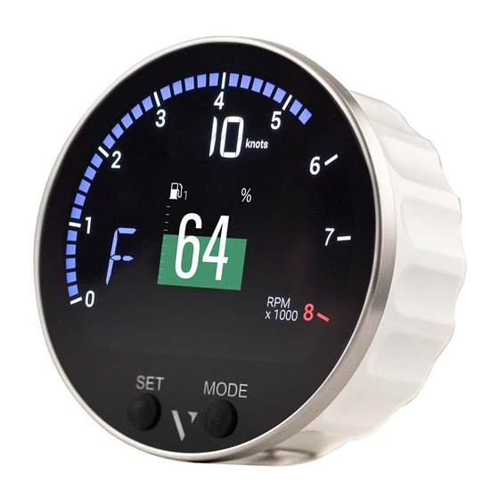
DESCRIPTION DESCRIPTION Part Description Display to show data pages and menu Engaged gear Current speed according to the selected unit of measurement Rev counter Alarm lights SET / Buttons to interact with the data pages and MODE the menu DATA SCREENS Single layout Data symbol Unit of measured value... - Page 13 GENERAL SETTINGS SCREENS SCROLLING To... Then... scroll through the pages To return to the previous page, briefly press the MODE button. • To go to the next page, briefly press the SET button. • adjust the backlight briefly press the SET and MODE buttons simultaneously reset a resettable value Press and hold the SET button until the value resets.
- Page 14 GENERAL SETTINGS Input signal Output Unit Icon/Text Information NMEA NMEA Internal Frequency Resistive EasyLink 2000 2000 Total fuel used L / gal. Fuel flow L / h / CONS Clear water % / L / FRESH Dark waters % / L / WASTE Voltmeter Ammeter...
- Page 15 GENERAL SETTINGS ENGINE HOURS In the absence of data received from the NMEA 2000 network, the indicator considers the internal data if it is greater than 300 RPM. In the presence of data from the NMEA 2000 network, the indicator considers the data received from the network only if higher than the internal data.
-
Page 16: General Settings
GENERAL SETTINGS GENERAL SETTINGS SETTINGS MENU STRUCTURE OPERATE THE SETTINGS MENU To... Then... enter the settings menu Press the SET button until the first menu item appears. scroll through the settings menu items and • To go to the previous item/value, briefly press the MODE button. possible values To go to the next item/value, briefly press the SET button. - Page 17 GENERAL SETTINGS UNITS MENU Setting Description Possible values/commands* Speed Speed units kmh/ mph/ kts TRIP Unit of measurement of distance travelled km / mile / nm Flow Flow measurement units ... lh / gph Tank Unit of measurement of the liquid in the tank l / US gal Temperatures Temperature units °C/ °F...
- Page 18 Press and hold the SET button until the value resets. UPLOAD A CUSTOM SPLASH LOGO A custom splash logo can be loaded from a PC using the veratron Configuration Tool. For more information, please refer to the veratron Configuration Tool user manual or contact your veratron reseller. B00xxxx...
-
Page 19: Sensors' Configurations
TYPES OF CALIBRATION Calibration of analog sensors can be: • Standard: only for veratron sensors. You define the type of sensor and the device reads with good approximation the value of the sensor without the need of calibration. • Manual: For non-Veratron sensors or to obtain a more accurate indication from a Veratron sensor. A three- or five- point procedure instructs the system to detect the sensor value. - Page 20 SENSORS CONFIGURATION SENSORS MENU STRUCTURE CALIBRATE THE SENSORS Fuel level sensor • Connect the sensor of interest. See Connecting an analogue sensor. • Under Sensors select the resistive input to which the sensor is connected. • Under Fuel > Sensor, choose the desired configuration type. •...
- Page 21 • In ... Choose the desired configuration type. • If you chose the CUSTOM configuration, create the sensor curve using the veratron Configuration Tool. Intelligent Battery Sensor (IBS) • Connect the sensor of interest. See Connecting the Intelligence Battery Sensor.
-
Page 22: Sensor Curves
RUDDER ANGLE SENSORS Here are the possible alternatives: 10-180 Ω Selectable value Curve 5-90 Ω Single Dual CUSTOM Three-step calibration wizard COOLANT TEMPERATURE SENSORS Here are the possible alternatives: 291-22 Ω Selectable value Curve 120° CUSTOM Calibration via veratron Configuration Tool B00xxxx... - Page 23 SENSOR CURVES OIL TEMPERATURE SENSORS Here are the possible alternatives: 197-11 Ω Selectable value Curve 150° CUSTOM Calibration via veratron Configuration Tool OIL PRESSURE SENSORS Here are the possible alternatives: 10-184 Ω Selectable value Curve 10-184 Ω 5 bar 10 bar...
-
Page 24: Alarms
ALARMS ALARMS ALARMS NOTIFICATION • The VMH35 indicator shows internal active alarms and The corresponding alarm lamp will light up, if those coming from NMEA 2000. The ALARMS item present. • allows you to set the alarms that can be generated by the The buzzer is activated, if connected and set. - Page 25 TECHNICAL DATA LIST OF MANAGED ALARMS Local alarms NMEA 2000 • • Engine Overtemp Water in fuel • • Battery low Engine Overtemp • • Overvoltage Battery low • • Battery low charge Low Oil Pressure • • Battery overtemp Check Engine •...
-
Page 26: Troubleshooting
TROUBLESHOOTING TROUBLESHOOTING DATA DISPLAY Problem Root cause Solution The values displayed Incorrect sensor configuration. Check the configuration in the Sensors menu. are not as expected. Sensor connected incorrectly. Check the connection, refer to the Installation Instructions. The NMEA 2000 network Check the connections and that there is a termination at backbone has not been created both the beginning and end of the backbone. -
Page 27: Technical Data
TECHNICAL DATA TECHNICAL DATA GENERAL FEATURES Material Mineral glass front lens Stainless steel frame Connectors • Molex MX150 (with EasyLink connector integrated in the pigtail cable) • NMEA 2000 Micro-C M12 • 2 analogue resistive inputs (0-400 Ω) Input data •... - Page 28 TECHNICAL DATA COMPLIANCE Compliance UKCA UL94 Directives 2014/30/EU (Electromagnetic compatibility) 2011/65/EU (Hazardous substances in electrical and electronic equipment) Reference standards IEC 60945: 2002-08 (environmental class: exposed) DISPOSAL RESPONSIBILITY Dispose of by separate collection through government or local government designated collection facilities. Proper disposal and recycling will help prevent potentially negative consequences for the environment and people.
-
Page 29: Spare Parts, Sensors And Accessories
Spin lock A2C13760900 EasyLink extension cable A2C59500139 Rubber gasket A2C14624100 ACCESSORIES Product Part Number Wiring harness for outboard engines B00106601 IBS (Intelligent Battery Sensor) 12 V Gen II B00084201 Adapter cable for IBS B00090601 For all available accessories, visit www.veratron.com. B00xxxx... - Page 30 - Print the document in its original format, in whole or in part. - Copy of contents without modification and declaration of Veratron AG as copyright owner. Veratron AG reserves the right to make changes or improvements to this documentation without notice. Requests for permission, additional copies of this manual, or technical information about this manual should be directed to veratron AG.
Need help?
Do you have a question about the VMH 35 and is the answer not in the manual?
Questions and answers