Table of Contents
Advertisement
Quick Links
Phone: 800-669-1303 or 801-561-0303
Fax: 801-255-2312
e-mail: treborservice@idexcorp.com
This manual contains information necessary for the safe and proper use of the Rev6. Included are specifications
for the standard configurations of the pump system and instructions regarding its use, installation, operation,
adjustment, inspection, and maintenance. For special configurations of the pump system, refer to accompanying
information. Please familiarize yourself with the contents of the manual to ensure the safe and effective use of
this product. After reading this manual, please store the manual where the personnel responsible for operating
the pump system can readily refer to it at any time.
SERIAL NUMBER (located on the product):
REV6
Operation / Maintenance
Manual
10/04/2017 – REV6-B
Advertisement
Table of Contents

Related Manuals for Idex Trebor REV6


Summary of Contents for Idex Trebor REV6
- Page 1 Phone: 800-669-1303 or 801-561-0303 Fax: 801-255-2312 e-mail: treborservice@idexcorp.com REV6 Operation / Maintenance Manual This manual contains information necessary for the safe and proper use of the Rev6. Included are specifications for the standard configurations of the pump system and instructions regarding its use, installation, operation, adjustment, inspection, and maintenance.
- Page 2 Table of Contents Safety Precautions ......................... 4 Specifications ..........................5 Specification of Components ....................5 Standard System Configurations ..................... 8 2.2.1 Pump Only Configuration ....................8 2.2.2 Stand-Alone System Configuration ................... 8 2.2.3 Extended System Configuration ..................9 General Environmental Conditions ..................10 Pump Performance Curves ....................10 2.4.1 Pressure-Flow Curves .....................10...
- Page 3 5.1.1 State Diagram of Standalone Controller ................30 5.1.2 Standalone Operation (Button Control Mode) ..............31 5.1.3 Extended Operation (Analog Control Mode) ..............31 5.1.4 Error Display on the Integrated Panel ................32 System Operation with Extended Controller (REV6A1) ............33 5.2.1 State Diagram of the PLC Interface ................
-
Page 4: Safety Precautions Caution
1 SAFETY PRECAUTIONS CAUTION Do not open the motor or controller. Trebor does not assume responsibility for any damage occurring under such circumstances. CAUTION High magnetic field strength of pump impeller The pump system contains a rotor magnet with high field strength. This may alter or damage the calibration of sensitive electronic devices and measuring instruments in the immediate surroundings. -
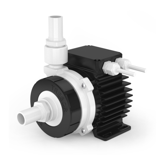
Page 5: Specification Of Components
2 SPECIFICATIONS 2.1 Specification of Components Figure 1 shows the main system components. The accessories are listed below. Figure 1 – Standard Components (Cables not shown) Each Rev6 pump system is comprised of a pump, a motor, a controller, and two fluid port adapters. Table 1 lists each part: Table 1 –... - Page 6 Component Item Description Materials of Construction M6x25mm Motor Mounting 98004269 316 stainless steel Screws QTY 4 Standalone Controller Standalone 48VDC/600W Power 98004271 Controller Panel control for motor speed Optional PLC control Controller Extended Controller Extended 98004275 48VDC/600W Power Controller PLC control Standard 3 meter cables included (not shown) Motor...
- Page 7 Table 3 – Fluid Port Adapters Seal Type Part Description Plant Connection G12000-10 GROUP;ADPTR;3/4IN PIPE;PTFE GSKT 3/4” weldable pipe G12F08-10 GROUP;ADPTR;1/2 IN FLR;PTFE GSKT 1/2” flare G12F12-10 GROUP;ADPTR;3/4FLR;PTFE GSKT;PVDF NUT 3/4” flare G12F16-10 GROUP;ADPTR;1IN FLR;PTFE GSKT 1” flare G12P12-10 GROUP;ADPTR;3/4 FNPT;PTFE GSKT 3/4”...
-
Page 8: Standard System Configurations
Accessory Description Comments TSP-600-148-M (M=Modified design from Traco) Power Output: 48 VDC, 600 W 98004274 POWER SUPPLY;48V;REV6 Supply Input: 85-265 VAC (auto detect) CE, CB, UL, CSA, SEMI F47 PP (+40% Talc) Air Cooling NPT 1/4” Connection 98004282 MODULE;AIR COOLING;REV6 Module 1-3 bar (14-43 psi) –... - Page 9 2.2.3 Extended System Configuration The extended version of the pump system (Figure 3) consists of a controller with an extended PLC interface. This allows setting the speed by an external signal and enables precise closed-loop flow or pressure control in connection with either a flow or a pressure sensor. A USB interface allows communication with a PC in connection with the Trebor Service Software.
-
Page 10: General Environmental Conditions
2.3 General Environmental Conditions Table 5 – Environmental Conditions for Pump System Controller usage Indoor Motor with pump usage Indoor/Outdoor Altitude Up to 2000 m Operating ambient temperature 0 to 40°C Storage ambient temperature -20 to 80°C (Extremes for transportation) Operating humidity range 15 to 95% relative humidity (non-condensing) Storage humidity range... - Page 11 2.4.2 NPSHr Curves 10.0 12.5 15.0 17.5 20.0 Specific gravity = 1 g/cm Viscosity = 1 cP 8000 Liquid Temp.: 20°C 7000 6000 5000 NPSHr Criteria ≡ The min. absolute inlet pressure where the pump pressure is reduced by 3% - Limitation is due to the axial limit of the impeller Figure 5 –...
-
Page 12: Basic Dimensions Of Main Components
2.5 Basic Dimensions of Main Components All dimensions are given in mm and inches with the inch measurement in brackets. Figure 7 – Basic Pump Dimensions REV6 OPERATION / MAINTENANCE MANUAL CONTENTS... - Page 13 Figure 8 – Alternative Mounting Position Figure 9 – Cable and Connector Specifications REV6 OPERATION / MAINTENANCE MANUAL CONTENTS...
- Page 14 Figure 10 – Controller Basic Dimensions 2.6 Air Cooling Module The motor can be cooled by using the air-cooling module. This module attaches to the back of the pump motor with four bolts. Section 3.4.1 gives more information on motor cooling requirements. Figure 11 shows the dimensions of the motor with the attached air-cooling module.
- Page 15 Figure 11 – Motor dimensions with attached air-cooling module. 2.7 Cable Minimum Bend Radius Cable Sensor Power Minimum Bending Radius Minimum Bending Radius Jacket Cable OD Cable OD Permanent Installation Occasional Cable Movement 6.6mm 8.4mm 7x Cable OD 15x Cable OD 7.2mm 10.0mm 6x Cable OD...
-
Page 16: Engineering Information
3 ENGINEERING INFORMATION 3.1 Sealing and Material Concept Figure 12 – Sealing and Material Concept Table 6 – Materials Used in the Pump and Motor Item System Materials Component Description Pump Casing PTFE Inlet Housing PTFE Union Nut Polypropylene Static Sealing O-ring of FFKM Pump Pump Casing... -
Page 17: Power Consumption
System Item Materials Component Description Flat gasket for motor FKM (FPM) housing Cable strain relief bushing PVDF, cable jacket is PVC Motor ETFE coating, waterproof (IP-67) Motor housing Coils and electromagnetic circuit potted with an epoxy compound (UL94 V0). 3.2 Power Consumption 10.0 12.5 15.0... -
Page 18: Temperature Monitoring
3.3 Temperature Monitoring To avoid overheating of the system, the controller and motor temperatures are monitored. If the controller temperature exceeds 70°C (158°F) or the motor temperature 90°C (194°F) for longer than 10 minutes, the system goes into an error state and the pump stops. At 80°C (176 F) controller temperature or 100°C (212°F) motor temperature, the system immediately stops. -
Page 19: Thermal Management
3.4 Thermal Management 3.4.1 Motor Temperature The motor temperature depends on the ambient and liquid temperature, as well as on the hydraulic operation point. Figure 16 and Figure 17 illustrate the temperature characteristics of the motor depending on these parameters. For higher fluid temperatures and hydraulic operating points, active cooling is recommended. - Page 20 Figure 18 – Temperature Curves of Motor with Air Cooling Module (98004282) Figure 19 – Fluid Temperature Influence on Motor Temperature (Measurement at 7000 RPM, 23 LPM but gradients are representative for other operational points) The above curves are measurements of the motor temperature at certain liquid and ambient temperatures.
- Page 21 ( ���� ) ≈ ���� ( ���� = 25℃ ) + ( ���� − 25℃ ) ∙ ∙ ( ���� − 25℃ ) ���� , ���� = 25℃, ���� ���� ���� ����������������� � ���� ���� ���� ���� ���� ���� ���� ��������...
- Page 22 3.5 Hydraulic Circuit Design Follow these general design rules for the hydraulic circuit will yield more robust pump operation and optimum priming: 1. The general rule for optimum priming behavior is to minimize the pressure drop in the inlet circuit and avoid negative pressure at the inlet of the pump. 2.
-
Page 23: Electrical Installation Of Controller
4 INSTALLATION 4.1 Electrical Installation of Controller 4.1.1 Overview The Rev6 standalone controllers have signal processor controlled power converters with four switched inverters for the drive and the bearing windings of the motor. The signal processor allows precise control of pump speed and impeller position. Figure 21 shows the interfaces of the standalone controller with standalone and minimal PLC functions. - Page 24 Item Interface Description “Power on” Green LED LED is on if supply voltage of signal electronics is present. “Power Output not Red LED is off if the switched output stage of the controller is enabled. If the LED is on, the active”...
- Page 25 Item Interface Description DC power input Torque spec. for tightening of connector screws on motor side: Min. = 0.5 “POWER INPUT” Nm, Max. = 0.6 Nm “Power on” Green LED LED is on if supply voltage of signal electronics is present. “Power Output not active”...
- Page 26 4.1.4 Electrical Installation of Standalone Controller for Extended Operation If the REV6A0 shall be controlled with external signals the “USER INTERFACE” can be used with the PIN designations described in Table 9. Table 9 – Description of “USER INTERFACE” Connector Function Name Levels...
- Page 27 4.1.5 Installation of PLC Interface for Extended Controller To operate the pump system with a PLC, a minimum set of two digital inputs and one analog input is needed. The digital and analog outputs can be used to monitor the pump status and operating parameters.
- Page 28 Connect Pin Name Designation Levels Note Pin # Analog In1, (Signal) Actual Process Control Value 4..20 mA = 0..100% (Current Input) Ground Analog In1 - Grounds are internally connected 4..20 mA = 0..10000 rpm (speed mode) Analog In2, (Signal) - Direct connection, no protection. ->...
-
Page 29: Mechanical Installation Of The Pump/Motor
4.2 Mechanical Installation of the Pump/Motor • The motor can be fixed with four screws on the motor feet (see Figure 7) • As an alternative the motor can be mounted with four screws on the back (see Figure 8) •... -
Page 30: Operation
5 OPERATION 5.1 System Operation with Standalone Controller 5.1.1 State Diagram of Standalone Controller The standalone controller allows operation with manual speed setting (Button Control Mode) as well as extended operation with analog speed setting (Analog Control Mode). Figure 27 shows the state diagram, which can be controlled with the manual buttons and the signals on the “USER INTERFACE”... - Page 31 5.1.2 Standalone Operation (Button Control Mode) • When applying power the system defaults into the “Button Control Mode” and goes into the status “OFF Button Control” according to Figure 27. Levitation is disabled and the display indicates “OF”. • Levitation can be enabled by pressing the “UP” button for 1 second (display shortly indicates “ON”) or by activating (typically 24V) the “ENABLE”...
- Page 32 5.1.4 Error Display on the Integrated Panel Error Errors Error Code Source on Display Motor No motor Er 01 Motor Motor cable (power wires) not connected to controller Er 02 Motor Motor cable (sensor wires) not connected to controller Er 03 Motor No impeller Er 04...
- Page 33 5.2 System Operation with Extended Controller (REV6A1) 5.2.1 State Diagram of the PLC Interface Power On Reset: active Status : not active State 1 Enable: active Reset: not active Enable : not active Process Mode : not active ERROR (Speed Control Mode) Enable: active Reset: not active Status : Active...
- Page 34 Effect on Designated Digital Error Source Errors Output of the PLC Error = relay open Motor No rotor Motor Temperature over 100°C Error = relay open Temperature was higher than 90°C for more than 10 Motor Error = relay open minutes.
-
Page 35: Inspection And Maintenance
6 INSPECTION AND MAINTENANCE 6.1 Impeller Replacement Interval The impeller has a limited lifetime depending on the type, concentration, and temperature of the fluid being pumped. Therefore, a preventive periodical exchange of the impeller is recommended. Contact the Trebor Technical Service Department (see Section 8) for further information on replacement times. 6.2 Impeller Replacement Procedure WARNING 6.2.1 Preparation... - Page 36 5. Inspect the wet area of the pump head 6.2.2 Instructions for Replacement carefully. In case of material damage, replace the pump casing and inlet housing. 6. Place the new impeller into the pump 1. Power down the pump system and remove the casing using the Impeller Removal Tool AC power.
-
Page 37: Troubleshooting
7 TROUBLESHOOTING 7.1 Troubleshooting for Operation with Standalone Controller For troubleshooting and failure analysis with the stand-alone controller the following procedure is recommended: • Check the status of the LEDs. The specific LEDs are described in Table 7 • Use the ERROR codes on the display. The specific error codes are described in Table 11. •... -
Page 38: Technical Support
8 TECHNICAL SUPPORT For troubleshooting, support and detailed technical information contact TREBOR 8100 South 1300 West West Jordan, Utah 84088 USA Tel: (801) 561 0303 Toll Free: (800) 669 1303 Fax: (801) 255 2312 REV6 OPERATION / MAINTENANCE MANUAL CONTENTS... -
Page 39: Regulatory Status
9 APPENDIX 9.1 Regulatory Status 9.1.1 CE Marking Machinery Directive 2006/42/EC (Safety) EMC Directive 2004/108/EC Electromagnetic Compatibility The Rev6 pump, in its various configurations as listed below, is in conformity with the above-mentioned European Directives. Part Name Description Rev6A0 Pump casing consisting of various fittings and o-rings See F0117C 98004270 Bearingless motor... -
Page 40: Symbols And Signal Words
9.2 Symbols and Signal Words Symbol / Description Type Source Signal Word Indication of an imminently hazardous situation that, if not DANGER avoided, will result in death or severe injury. Limited to the Signal word SEMI S1-0701 most extreme situation Indication of a potentially hazardous situation, which if not WARNING Signal word...
Need help?
Do you have a question about the Trebor REV6 and is the answer not in the manual?
Questions and answers