Table of Contents
Advertisement
Quick Links
Advertisement
Table of Contents

Subscribe to Our Youtube Channel
Related Manuals for Co2meter CM-650


Summary of Contents for Co2meter CM-650
- Page 1 CM-650 Welding Gas Analyzer USER MANUAL Revision C...
-
Page 2: Table Of Contents
WELDIING GAS ANALYZER CM-650 5/21/2021 Table of Contents Product Overview ..............3 Package Content & Unit Layout ..........4 Contents ..................4 Internal Features ..............4-5 External Features..............5-6 Operation ................... 6 Installation Procedure..............7 System Functionality Test Procedure ........8 Specifications. -
Page 3: Product Overview
CM-650 5/21/2021 Product Overview Thank you for selecting the CM-650 Welding Gas Analyzer. The Welding Gas Analyzer device was designed to indicate proper CO2 concentrations of welding gas mixtures. The device features two standard ¼ inch NPT inlet ports to allow the user to monitor the concentration of the shield gas before and during welding operations. -
Page 4: Package Content & Unit Layout
WELDIING GAS ANALYZER CM-650 5/21/2021 Package Content & Unit Layout The CM-650 package comprises the following parts: • NEMA 4 Enclosure, CM-650 Gas Analyzer • (1x) 12 ft. relay cable • (1x) 12 ft. power cable • (2x) 5/8-18 LH x ¼ Male fittings •... -
Page 5: External Features
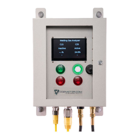
WELDIING GAS ANALYZER CM-650 5/21/2021 D. 25% Green confirmation light: indicates when proper CO2 concentration is present in the 25% port E. 25% Red warning light: indicates when unsuitable CO2 concentration is present in the 25% port F. USB port: Used to remove data log files. -
Page 6: Operation
WELDIING GAS ANALYZER CM-650 5/21/2021 3. Log Button: Used to force a data log reading to be saved to the data log file. 4. Power In: Connection port for the power cable. 5. Signal Out: Connection port for the signals sent out. Used to control strobe. -
Page 7: Installation Procedure
WELDIING GAS ANALYZER CM-650 5/21/2021 Installation Procedure This device features four mounting feet to allow for easy installations for an array of applications. ***Mounting hardware not included*** 1. Mount the device securely in desired location. Pay close attention to the orientation of the device. -
Page 8: System Functionality Test Procedure
WELDIING GAS ANALYZER CM-650 5/21/2021 System Functionality Test Procedure: 1. Connect Welding Gas Analyzer to Power Supply and wait for initialization. 2. Connect 15% CO2/Argon Calibration Gas to 15% Inlet Port of the Welding Gas Analyzer. 3. Adjust calibration gas pressure regulator to 40 psi. -
Page 9: Specifications
WELDIING GAS ANALYZER CM-650 5/21/2021 Specifications • CO2 Sensing Method: Non-dispersive infrared (NDIR) absorption • Measurement Range: 0-100% • Accuracy @ 100% Range: ±300 ppm +/-5% of reading @ STP • Resolution: 1,000pm • Non Linearity: < 1% of FS •... -
Page 10: Downloading Data
WELDIING GAS ANALYZER CM-650 5/21/2021 Downloading Data: Located internally, on the front panel of the device, there is a protected UBS port. Remove Cap and insert USB drive into port to begin data log download. Data logs are saved as .CSV files. -
Page 11: Calibration
5/21/2021 Calibration: The CM-650 Welding Gas Analyzer is calibrated at CO2 Meter prior to being shipped. It is recommended that the device be calibrated annually to maintain optimal functionality. 1. Connect certified 15% or 25% calibration gas to desired port to be calibrated. The 15% and 25% ports must be calibrated individually. -
Page 12: Troubleshooting
WELDIING GAS ANALYZER CM-650 5/21/2021 Document History Date Revision Description 20 December, 2017 Initial Draft 30 December, 2019 Initial Release 21 May, 2021 Publishing, Formatting, Confirmation Troubleshooting and Safety Precautions DISCLAIMER: Your safety is very important to us. To ensure the proper and safe use of the device, please ensure to read all warnings and the entire User Manual prior to using the device. -
Page 13: Product Care & Contact Info
To ensure maximum benefit from this product, please observe the follow guidelines. 1. Repair - Do Not attempt to repair or modify the device in any way. Please contact CO2Meter directly if the product needs servicing, including replacement or calibration service. See Section 15 for technical support contact information.
Need help?
Do you have a question about the CM-650 and is the answer not in the manual?
Questions and answers