
Related Manuals for Home Decorators Collection SW19110 BN


Summary of Contents for Home Decorators Collection SW19110 BN
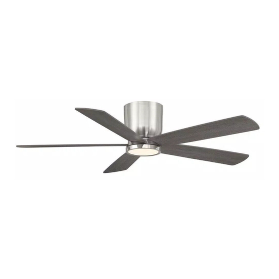
- Page 1 SKU/Model : #XXXX/#SW19110 MWH #XXXX/#SW19110 MBK #XXXX/#SW19110 BN BRITTON LED 52 IN. CEILING FAN...
- Page 4 We warrant the fan motor to be free from defects in workmanship and material present at time of shipment from the factory for a period of lifetime after the date of purchase by the original purchaser. And we warrant the LED light kit to be free from defects in workmanship and material present at time of shipment from the factory for a period of years after the date of purchase by the original purchaser.
- Page 5 15+1 spare Fiber washer 15+1 spare Flywheel screw 5+1 spare Remote control holder mounting screw Mounting plate screw (pre-assembled) Fan housing screw (pre-assembled)
- Page 6 Fan blades 21W LED assembly Fan housing Mounting plate (pre-assembled) Receiver with extension wire (pre-assembled) Fan motor assemby Flywheel...
- Page 8 Remove the mounting plate screw (GG) from the mounting bracket (B) and loosen the other three mounting plate screws (GG) approximately 1/4 turn. Keep the mounting plate screw (GG) that removed aside for use later. Lift the fan motor assembly (F) by hanging the square hole (KK) of the mounting plate (D) on the hook (JJ) from the mounting bracket (B) allowing it to hang.
-
Page 9: Electrical Connections
Electrical connections wire nuts (DD) Note: For easy installation, the receiver (E) with extension wire (LL) is pre-intalled on the mounting plate (D). receiver (E). receiver (E). Connect the ground wire (green or bare copper) of the outlet box to the ground wire of the mounting plate (D) and the ground wire of the mounting bracket (B). - Page 10 Installing the fan motor assembly Lift and place the key holes (MM) of the mounting plate (D) over the three screws (GG) previously loosened on the mounting bracket (B) and turn the mounting plate (D) until it locks in place and no longer turns. Secure by tightening the three screws (GG) previously loosened and the screw (GG) previously removed.
- Page 11 Installing the fan housing Align the four large screws (HH) pre-locked on the fan housing (C) to the slotted holes (NN) of the mounting bracket (B). Turn the fan housing (C) at the right side and twist the screws (HH) to the end of the slotted holes (NN) until they lock in place and no longer turn.
- Page 12 flywheel Tighten the flywheel (G) onto the bottom of fan motor assembly (F) by using the five flywheel screws (CC).
- Page 13 Installing the fan blades to the flywheel Insert the blade (A) through the slot on the flywheel (G). Fasten the fan blade (A) to the flywheel (G) by using the three blade screws (AA) and the three fiber washer (BB) and tighten them securely. Repeat this step for the other four blades.
- Page 14 CAUTION: To Reduce The Risk Of Electric Shock, Disconnect The Electrical Supply Circuit To The Fan Before Installing The Light Kit. Attach the LED assembly (H) to the locking plate (PP) of fan motor assembly (F) by twisting tightly.
- Page 15 reverse button (QQ): Note: To operate the reverse function on this fan, press the reverse button when the fan is running.
- Page 17 Check the wires with the molex plugs to ensure proper connection. Balancing kit included additional instruction manual within the packet.
- Page 18 Fan blades Fiber washer Fan housing Flywheel screw Mounting plate (pre-assembled) Receiver with extension wire Remote control holder mounting screw (pre-assembled) Fan motor assemby Mounting plate screw (pre-assembled) Flywheel Fan housing screw (pre-assembled) 21W LED assembly...
- Page 19 CF552HR-01...
Need help?
Do you have a question about the SW19110 BN and is the answer not in the manual?
Questions and answers
We have bought 5 Britton 52inch fan Home decor. However the remote we are using in one room turns on/off in another room. How do we separate these functions to each individual fan/remote.
Can I pass a wire through to control the light kit from separate wall switch? Is there a diagram to demonstrate this?