Advertisement
®
Installation, Operation and Maintenance Manual
Please read and save these instructions for future reference. Read carefully before attempting to assemble, install,
operate or maintain the product described. Protect yourself and others by observing all safety information. Failure
to comply with these instructions will result in voiding of the product warranty and may result in personal injury
and/or property damage.
Energy recovery cores are certified by the AHRI Air-to-Air Energy Recovery Ventilation Equipment Certification
Program in accordance with AHRI Standard 1060. Actual performance in packaged equipment may vary.
Certified Ratings are available in the Certified Product Directory at www.ahridirectory.org
General Safety Information
Only qualified personnel should install this system.
Personnel should have a clear understanding of these
instructions and should be aware of general safety
precautions. Improper installation can result in electric
shock, possible injury due to coming in contact with
moving parts, as well as other potential hazards.
Other considerations may be required if high winds
or seismic activity are present. If more information is
needed, contact a licensed professional engineer before
moving forward.
DANGER
Always disconnect power before working on or near
this equipment. Lock and tag the disconnect switch or
breaker to prevent accidental power up.
CAUTION
When servicing the unit, the internal components may
be hot enough to cause pain or injury. Allow time for
cooling before servicing.
CAUTION
Precaution should be taken in explosive atmospheres.
®
Energy Recovery Technical Support
Call 1-800-240-0870
1. Follow all local electrical and safety codes, as well as
the National Electrical Code (NEC), the National Fire
Protection Agency (NFPA), where applicable. Follow
the Canadian Electrical Code (CEC) in Canada.
2. All moving parts must be free to rotate without
striking or rubbing any stationary objects.
3. Unit must be securely and adequately grounded.
4. Do not spin fan wheel faster than maximum
cataloged fan RPM. Adjustments to fan speed
significantly effects motor load. If the fan RPM is
changed, the motor current should be checked
to make sure it is not exceeding the motor
nameplate amps.
5. Do not allow the power cable to kink or come in
contact with oil, grease, hot surfaces or chemicals.
Replace cord immediately if damaged.
6. Verify that the power source is compatible with
the equipment.
7. Never open access doors to the unit while it
is running.
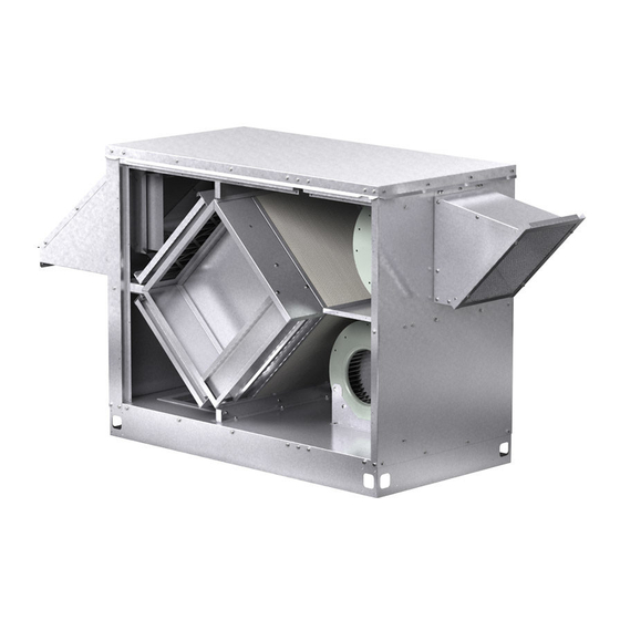
Document 480955
Model ECV
Energy Core Ventilator
Energy Core Ventilator
1
Advertisement
Table of Contents

Related Manuals for Greenheck ECV Series


Summary of Contents for Greenheck ECV Series
- Page 1 Document 480955 Model ECV Energy Core Ventilator ® Installation, Operation and Maintenance Manual Please read and save these instructions for future reference. Read carefully before attempting to assemble, install, operate or maintain the product described. Protect yourself and others by observing all safety information. Failure to comply with these instructions will result in voiding of the product warranty and may result in personal injury and/or property damage.
-
Page 2: Table Of Contents
Table of Contents Unit Overview Unit Overview ..... 2 Basic Unit Receiving, Handling and Storage ... 3 The unit is prewired such that when a call for outside air Installation . - Page 3 Receiving The unit should be stored at least 3½ in. (89 mm) off the floor. Clearance should be provided to permit air This product may have been subject to road salt circulation and space for inspection. during transit. If so, immediately wash off all visible Outdoor white reside from all exterior surfaces.
-
Page 4: Installation
Installation Outdoor Mounting Options EXHAUST AIR EXHAUST AIR DISCHARGE DISCHARGE SUPPLY AIR DISCHARGE SUPPLY AIR DISCHARGE OUTDOOR OUTDOOR AIR INTAKE AIR INTAKE RETURN AIR INTAKE RETURN AIR INTAKE Outdoor Air Discharge Bottom Outdoor Air Discharge End Indoor Mounting Options EXHAUST AIR EXHAUST AIR DISCHARGE DISCHARGE... - Page 5 Service Clearances The ECV unit requires minimum clearances to perform routine maintenance, such as filter replacement and energy core inspection. Blower and motor assemblies, energy recovery core and filter sections are always provided with a service door or panel for proper component access. Clearances for component removal may be greater than the service clearances, refer to drawing below for these dimensions.
- Page 6 Access Panel Locations The ECV is provided with access panels on both sides of the unit. The non electrical side can be placed against a wall. Clearance to the electrical side is essential to provide access to the control center and component maintenance.
- Page 7 Roof Curb Mounting Curb Outside Dimensions and Weights Rooftop units require curbs to be mounted first. The duct connections must be located so they will be clear of structural members of the building. 1. Factory Supplied Roof Curbs: Roof curbs are Model GKD.
- Page 8 POOR GOOD POOR GOOD Rail Mounting / Layout Ductwork Connections • Rails designed to handle the weight of the unit Examples of poor and good fan-to-duct connections should be positioned as shown on the diagram are shown. Airflow out of the fan should (rails by others).
-
Page 9: Electrical Information
Electrical Information WARNING The unit must be electrically grounded in accordance To prevent injury or death due to electrocution with the current National Electrical Code, or contact with moving parts, lock disconnect ANSI/NFPA 70. In Canada, use current CSA Standard switch open. - Page 10 Typical Control Center Components Optional Accessory Wiring Schematics Remote Panel 1. Main Disconnect (nonfusible, lockable) The remote panel is available with a number of different 2. Motor Starter – Exhaust Air Fan 3. Motor Starter – Outdoor Air Fan alarm lights and switches to control the unit. The remote panel ships loose and requires mounting and wiring in 4.
- Page 11 Dirty Filter Indicator (powered by others) Motor Potentiometer/0-10 VDC Fan Motor Control Model ECV-10-VG (reference unit wiring diagram) CLOSED 115-120V OPEN 208-230/277V BLACK 2CBL-M1 2CBL-M1 BLACK BLACK 0-10VDC WHITE ORANGE SUPPLY FAN MOTOR CLOSED 115-120V OPEN 208-230/277V BLACK 2CBL-M2 2CBL-M2 BLACK BLACK 0-10VDC...
-
Page 12: Optional Component Overview
Optional Component Overview Variable Frequency Drives (VFD) VFDs are used to control the speed of the fan as either Economizer multi-speed or modulating control. Multi-speed VFDs The energy core operation can be altered to take reference a contact which can be made by a switch or advantage of economizer operation (free cooling). -
Page 13: Start-Up
Start-Up Pre Start-Up Checklist – check as items are completed. DANGER o Disconnect and lock-out all power switches o Remove any foreign objects that are located in the Electric shock hazard. Can cause injury or death. energy recovery unit. Before attempting to perform any service or maintenance, turn the electrical power to unit to OFF o Check all fasteners, set-screws, and locking collars at disconnect switch(es). - Page 14 Optional Accessories Checklist Refer to the respective sections in this Installation, Operation and Maintenance Manual for detailed information. Refer to wiring diagram in unit control center to determine what electrical accessories were provided. Provided with Unit? Frost Control Application / Operation section: Setting Factory Default Frost Control thermostat...
-
Page 15: Start-Up Components
CAUTION When operating conditions of the fan are to be changed (speed, pressure, temperature, etc.), consult Greenheck to determine if the unit can operate safely at the new conditions. Start-up technician must check blower amperage to ensure that the amperage listed on the motor nameplate is not exceeded. -
Page 16: Optional Start-Up Components
Optional Start-Up Components Economizer Relevant Set Points Dirty Filter Switch 1. MAT SET The outdoor air temperature set point Setscrew (on front of switch) must after the energy core. The control will open/close be manually adjusted after the the bypass damper to maintain temperature as system is in operation. - Page 17 ® Vari-Green Electronically Frost Control Test Procedure Commutated (EC) Motor Timed Exhaust 1. Remove power from unit. Features 2. Jumper the temperature indicating sensor in the unit Soft Start – All motors control center. Thermostat controller has a pre-set feature soft-start technology temperature of 36ºF.
- Page 18 0 VDC CONTROL SIGNAL (BY OTHERS) 0-10 VDC CONTROL SIGNAL (BY OTHERS) A1 AC a few set points are changed at Greenheck and are RED TO A1 (+) AND AC (COMMON) WIRED TO A1 (+) AND AC (COMMON) 0-10 VDC CONTROL SIGNAL (BY OTHERS) shown in the tables.
-
Page 19: Routine Maintenance
Routine Maintenance Maintenance Procedures: Lubrication DANGER Check all moving components for proper lubrication. Electric shock hazard. Can cause injury or death. Apply lubrication where required. Any components Before attempting to perform any service or showing excessive wear should be replaced to maintain maintenance, turn the electrical power to unit to OFF the integrity of the unit and ensure proper operation. - Page 20 Fiber Membrane ordered). Filters should be checked and cleaned on a regular basis for best efficiency. The frequency of Frequency of cleaning - A regular cleaning cycle cleaning depends upon the cleanliness of the incoming must be established for the energy recovery core in air.
-
Page 21: Troubleshooting
Troubleshooting - Economizer Alarms Addressing Alarms Alarms will signify a faulty sensor. When this occurs, verify all connections to the sensor and controller are secure. Press enter twice to clear the alarm. If the issue persists, consult the factory. Clearing Alarms Once the alarm has been identified and the cause has been removed (e.g. - Page 22 Troubleshooting – Airflow Test and Balance Report The Test and Balance Report (TAB) is utilized to determine whether the appropriate amount of outdoor air and exhaust air is being supplied and removed from a building, respectively. There are no set rules on what information must be included in a TAB report.
- Page 23 Troubleshooting – Unit Symptom Possible Cause Corrective Action Replace fuse or reset circuit breaker and check Blown fuse or open circuit breaker. amps. Defective motor or capacitor. Replace. Blower fails to operate Motor starter overloaded. Reset starter and check amps. Check for On/Off switches.
-
Page 24: Our Commitment
As a result of our commitment to continuous improvement, Greenheck reserves the right to change specifications without notice. Product warranties can be found online at Greenheck.com, either on the specific product page or in the literature section of the website at Greenheck.com/Resources/Library/Literature.
Need help?
Do you have a question about the ECV Series and is the answer not in the manual?
Questions and answers