
Subscribe to Our Youtube Channel
Related Manuals for EMC Celerra NS20FC


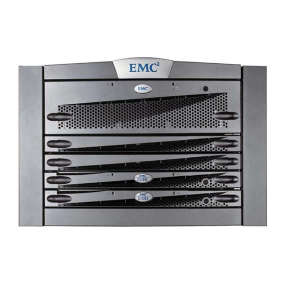
Summary of Contents for EMC Celerra NS20FC
- Page 1 Celerra NS20FC System ® ® (Dual Blade with FC Option Enabled) Installation Guide P/N 300-007-636 Rev A01...
- Page 2 EMC believes the information in this publication is accurate as of its publication date. The information is subject to change without notice. THE INFORMATION IN THIS PUBLICATION IS PROVIDED “AS IS.” EMC CORPORATION MAKES NO REPRESENTATIONS OR WARRANTIES OF ANY KIND WITH RESPECT TO THE INFORMATION IN THIS PUBLICATION, AND SPECIFICALLY DISCLAIMS IMPLIED WARRANTIES OF MERCHANTABILITY OR FITNESS FOR A PARTICULAR PURPOSE.
-
Page 3: Before You Begin
255.255.255.0 IP address of storage processor A 128.221.252.200 IP address of storage processor B 128.221.253.201 Gateway IP address of storage processor A 128.221.252.104 Gateway IP address of storage processor B 128.221.253.104 For more information, refer to Celerra Tools on http://Powerlink.EMC.com... -
Page 4: Installation Overview
Step 3. Install the Celerra Startup Assistant. Step 4. Register with the service provider. Step 1. Order the product and prepare the site. Implementation Step 5. Configure for production. For more information, refer to Celerra Tools on http://Powerlink.EMC.com... -
Page 5: Installation Steps
About 40 minutes. Note: If your Celerra NS20FC system arrives at your site in a pre-installed cabinet and is previ ously cabled, verify the cabling before you begin the use of your system. - Page 6 Unpacking the Celerra NS20FC system If your Celerra NS20FC system was purchased and shipped in an EMC 40 Unit cabinet, (70 in. tall, where 1 unit = 1.75 in.), start on page 11 of this document and confi rm that the cables are installed correctly and securely;...
- Page 7 Media kit inventory list Accessory kit docs and bezels Applications and Tools CD Power cables Software CD Standby power supply interconnect cable kit User documentation CD Crossover cable Getting Started with Celerra Serial cable For more information, refer to Celerra Tools on http://Powerlink.EMC.com...
- Page 8 S n t r e s s r o c s u r r a g c l o S t o B l a CIP-001034MOD For more information, refer to Celerra Tools on http://Powerlink.EMC.com...
- Page 9 Front of your rack CNS-000854 3. Do not fully tighten the two initial screws that join the rails to the rack. Allow some adjustment space for the installation of the components. For more information, refer to Celerra Tools on http://Powerlink.EMC.com...
- Page 10 Rail catch Screw (1 per side) Storage processor enclosure and blade enclosure Front Install the lower screw first screws (2 per side). Indentation to center of the rack Snap on bezels CIP-001033MOD For more information, refer to Celerra Tools on http://Powerlink.EMC.com...
- Page 11 3 Fibre Storage processor enclosure SP A 3 Fibre 2 Fibre 3 Fibre 2 Fibre SP B SP A 3 Fibre Blade 3 Blade 2 Blade 3 Blade 2 Blade enclosure CIP-001062 For more information, refer to Celerra Tools on http://Powerlink.EMC.com...
- Page 12 Cabling the EMC Celerra NS20FC system Cable the Celerra NS20FC standby power supply and modem ports. SP A SPS A This is the cable for optional standby power supply B. To external phone line SP B SPS B Modem Modem...
- Page 13 Cabling the EMC Celerra NS20FC system Cable the Celerra NS20FC private LAN cables. Control Station Standby power supply Storage processor SP B SP A enclosure Blade 3 Blade 2 Blade enclosure CIP-001077MOD For more information, refer to Celerra Tools on http://Powerlink.EMC.com...
- Page 14 Blade enclosure Blade 3 Blade 2 To public LAN To public LAN CIP-001133 Note: Attach customer-provided Ethernet cables from your external LAN to blade 2 and blade 3 (cge0) ports. For more information, refer to Celerra Tools on http://Powerlink.EMC.com...
- Page 15 PRI A connector HSSDC2 connector HSSDC2 connector Control Station (CS) Standby power supply (SPS) Storage processor enclosure (SP) SP B SP A connector Blade enclosure connector Pull/ Pull/ 21FC-22FC release tab release tab For more information, refer to Celerra Tools on http://Powerlink.EMC.com...
- Page 16 Cabling the EMC Celerra NS20FC system Cable extra Celerra NS20FC disk-array enclosures. Disk-array enclosure (DAE) Optional Disk-array enclosure (DAE) Optional Disk-array enclosure (DAE) Control Station (CS) Standby power supply (SPS) Storage processor enclosure (SP) Blade enclosure For more information, refer to Celerra Tools on http://Powerlink.EMC.com...
- Page 17 Standby power supply B (SPS B) is optional. If SPS B is used, plug the B-side power supplies on the storage processor enclosure (SPE) and disk-array enclosure (DAE) into SPS B, and plug SPS B into the left-side power distribution panel (PDP) on your cabinet. For more information, refer to Celerra Tools on http://Powerlink.EMC.com...
- Page 18 046-002-853_A02 SP B SP A SP B BE 0 SP A BE 0 Blade 2 Blade 3 10/100 10/100 046-002-842_A01 046-002-842_A01 BE 0 BE 1 BE 0 BE 1 Blade 3 For more information, refer to Celerra Tools on http://Powerlink.EMC.com...
- Page 19 Celerra Startup Assistant worksheet Verify that the site is properly prepared for your Celerra System. Complete the worksheets and use the information to verify the values when you run the Celerra Startup Assistant (CSA). Note: The CSA pre-populates values based on auto-discovery. Shaded values are values that will be auto-discovered based on your system and network environment;...
- Page 20 Celerra Startup Assistant worksheet Complete the confi guration wizard worksheets and use the information to verify the values when you run the Celerra Startup Assistant. 6. Record the licenses that you have purchased. Prompt Values □ Advanced Celerra Manager □ CIFS (Windows) □...
- Page 21 If you do not have access to the Powerlink website, insert the Celerra Network Server Applications and Tools CD onto your computer and the EMC Product Installation window opens. Celerra Startup Assistant to install the CSA on your computer.
- Page 22 Double-click the Celerra Startup Assistant shortcut on the desktop to launch CSA or go to C:\ProgramFiles\EMC\CSA\startup\launch.bat to run the Celerra Startup Assistant. The Celerra Startup Assistant guides you through the remaining steps. 3. Click Next. For more information, refer to Celerra Tools on http://Powerlink.EMC.com...
- Page 23 Add additional host for Fibre Channel enabled systems • Perform Common Post-CSA tasks At the end of each confi guration your system will be usable and ready for production. Note: These procedures create very basic implementations. For more information, refer to Celerra Tools on http://Powerlink.EMC.com...
Need help?
Do you have a question about the Celerra NS20FC and is the answer not in the manual?
Questions and answers