Advertisement
Quick Links
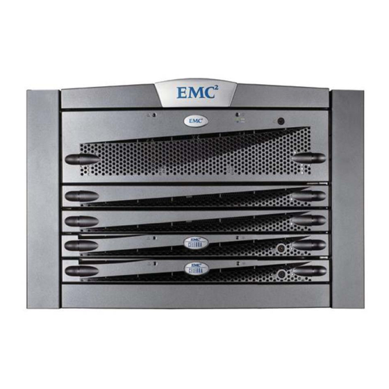
Setting Up the EMC
1
Before You Begin
Shipping Rack
Disk-array enclosure
Standby power supply
Control Station
LAN1
LAN2
Storage processor
enclosure
Blade enclosure
2
Install Rails and Components in Rack
2a Install Blade Enclosure
Required parts:
• Blade enclosure number for the NS21 single blade is P/N 100-520-336
or NS22 dual blade is P/N 100-520-334
• Adjustable rail kit P/N 100-561-802
• Bezel
Adjustable rail
2
Right front
Screw
Mounting
rail
3
Enclosure
Front
2b Install Storage Processor Enclosure
Required parts:
• Storage processor enclosure P/N 100-520-622 or P/N 100-520-623
• Rail kit P/N 100-561-802
Storage processor
SP B
enclosure
Blade enclosure
Blade 3 (B 3)
1. In the 1U space above the blade enclosure, install the storage processor
enclosure as described in
Step 2a Install Blade Enclosure.
Copyright © 2007 EMC Corporation. All rights reserved.
Front
Before you begin:
• The NS20 system you are about to install comes factory pre-loaded with Celerra Network Server software (DART) and
Storage Array software (FLARE).
is required, perform it after installation. For more information refer to Solution Case emc163261.
• Go to the Celerra Tools page for the latest information on the NS20 product: (http://Powerlink.EMC.com and select
Celerra Tools in the Navigator).
•
Two people are required to lift several hardware components.
• Remove
yourself or damage the equipment.
CIP-000935a
Required tools:
• Flathead screwdriver
• Manual Phillips-head screwdriver
Avoid stripping the screw-heads.
Rear
Alignment
pin
Right rear
Front
Mounting rail
CIP-000921
Rear
CIP-000922
SP A
A
B
B 2
CIP-000896
Celerra
®
DO NOT PERFORM A FRESH INSTALL OF
only
the 16 visible Phillips-head screws on the front of the mini-rack. Do not remove any of the other screws or you may injure
4
Screw
(2 per side)
Alignment
pin
Bezel
Screw (2)
Alignment
pin
1. Select 7U (12.25 in.) of available rack space for the NS20, plus 3U (5.25 in.) for each optional disk-array enclosure
(1U =1.75 inches).
NOTE: Use the supplied clip nuts if required for your rack.
2.
Starting at the bottom of the selected rack space,
a. From the cabinet front, insert the rail alignment pin into the middle hole of the 1U space on the right side at the
rear of the cabinet. Orient the rails so the sliding insert faces the inside of the rack.
b. Extend the rail to the front of cabinet, aligning the rail holes with the channel holes (the verticle metal bar with
evenly spaced holes) on the inside of the cabinet.
c. Install
one of the provided screws in the top hole on the front of the rail through the cabinet channel.
but do not tighten
d. From the cabinet rear, insert
but do not tighten
cabinet channel.
e. Repeat steps b-e to install the left rail.
3.
Two people are required for this installation:
of another
person, slowly slide the blade enclosure into the rails until the front assembly flanges are flush with the cabinet channels.
4.
Do not insert any new
screws, but tighten the screws on each end securing the mounting rails to the cabinet channels.
5. Insert two of the provided screws into the middle and bottom holes of each rail catch. Attach the bezel rail catches to the holes
in the rail flanges on the front of the cabinet. Then press the bezel onto the rail catches until it snaps into place.
2c Install Control Station
Required parts:
• Control Station P/N 100-520-606
• Rail kit P/N 100-520-527
• Adjustable Rail Installation kit
Control Station
Storage processor
enclosure
Blade enclosure
NOTE: Do not remove the Control Station label at this time.
1. In the 1U space above the storage processor enclosure,
install the Control Station as described in
1
NS20 System
®
SOFTWARE. If a software upgrade (not fresh install)
When installing the disk-array enclosures in the cabinet, do not remove the disks.
Enclosure
Rail
catch
Front
Indentation
to center of
the rack
mount one set of 1U rails for the blade enclosure as follows:
Always ensure the rail is level.
two screws in the top and bottom holes on the rail back through the
From the cabinet front, align the blade enclosure with the mounting channels.
SP B
A
B
Blade 3
Step 2a Install Blade
Rear
CIP-000923
With the help
SP A
Blade 2
CIP-000897
Enclosure.
300-004-900 Rev A01
Advertisement

Related Manuals for EMC Celerra NS20


Summary of Contents for EMC Celerra NS20
- Page 1 For more information refer to Solution Case emc163261. Storage processor enclosure • Go to the Celerra Tools page for the latest information on the NS20 product: (http://Powerlink.EMC.com and select Celerra Tools in the Navigator). Blade enclosure •...
- Page 2 Install Rails and Components in Rack (continued) 2d Install Standby Power Supply Standby power supply (SPS) Required parts: Control Station • Standby power supply (SPS). • Adjustable rail kit P/N 100-561-816 Storage processor • Adjustable rail installation kit with Phillips-head screws SP A enclosure SP B...
- Page 3 Connect Cables 3a Blade Fibre Channel Cables Required cables: • Two or four optical cables. Single blade NS20 or NS20FC systems only use two cables (cable 1 and 2). Refer to the Sales Order to determine the number of blades. Disk-array enclosure If there is a model NS21C-A or NS21C-A -FD on the Sales Order, you are installing a single blade system.
- Page 4 1. Remove the tear away label on the front of the Control Station. You need this for the Celerra Startup Assistant. 2. Insert the Celerra Network Server Applications and Tools CD, into the client computer. EMC Product Installation window opens.
Need help?
Do you have a question about the Celerra NS20 and is the answer not in the manual?
Questions and answers