
Related Manuals for Nokia RM-701


Summary of Contents for Nokia RM-701
- Page 1 Nokia Customer Care Service Manual RM-701 (Nokia 600; L3&4) Mobile Terminal Part No: (Issue 1) COMPANY CONFIDENTIAL Copyright © 2011 Nokia. All rights reserved.
- Page 2 RM-701 Amendment Record Sheet Amendment Record Sheet Amendment No Date Inserted By Comments Issue 1 08/2011 Page ii COMPANY CONFIDENTIAL Issue 1 Copyright © 2011 Nokia. All rights reserved.
- Page 3 Nokia operates a policy of continuous development. Nokia reserves the right to make changes and improvements to any of the products described in this document without prior notice. Under no circumstances shall Nokia be responsible for any loss of data or income or any special, incidental, consequential or indirect damages howsoever caused.
- Page 4 WCDMA networks and cause problems to 3G cellular phone communication in a wide area. • During testing never activate the GSM or WCDMA transmitter without a proper antenna load, otherwise GSM or WCDMA PA may be damaged. Page iv COMPANY CONFIDENTIAL Issue 1 Copyright © 2011 Nokia. All rights reserved.
- Page 5 Use only approved accessories and batteries. Do not connect incompatible products. CONNECTING TO OTHER DEVICES When connecting to any other device, read its user’s guide for detailed safety instructions. Do not connect incompatible products. Issue 1 COMPANY CONFIDENTIAL Page v Copyright © 2011 Nokia. All rights reserved.
- Page 6 RM-701 ESD protection ESD protection Nokia requires that service points have sufficient ESD protection (against static electricity) when servicing the phone. Any product of which the covers are removed must be handled with ESD protection. The SIM card can be replaced without ESD protection if the product is otherwise ready for use.
- Page 7 All of the above suggestions apply equally to the product, battery, charger or any accessory. Issue 1 COMPANY CONFIDENTIAL Page vii Copyright © 2011 Nokia. All rights reserved.
- Page 8 Our policy is of continuous development; details of all technical modifications will be included with service bulletins. While every endeavour has been made to ensure the accuracy of this document, some errors may exist. If any errors are found by the reader, NOKIA MOBILE PHONES Business Group should be notified in writing/e- mail. Please state: •...
- Page 9 Batteries' performance is particularly limited in temperatures well below freezing. Do not dispose of batteries in a fire! Dispose of batteries according to local regulations (e.g. recycling). Do not dispose as household waste. Issue 1 COMPANY CONFIDENTIAL Page ix Copyright © 2011 Nokia. All rights reserved.
- Page 10 RM-701 Battery information (This page left intentionally blank.) Page x COMPANY CONFIDENTIAL Issue 1 Copyright © 2011 Nokia. All rights reserved.
- Page 11 1 General Information 2 Service Tools and Service Concepts 3 BB Troubleshooting and Manual Tuning Guide 4 Cellular RF troubleshooting 5 Camera Module Troubleshooting 6 System Module Glossary Issue 1 COMPANY CONFIDENTIAL Page xi Copyright © 2011 Nokia. All rights reserved.
- Page 12 RM-701 Nokia 600; L3&4 Service Manual Structure (This page left intentionally blank.) Page xii COMPANY CONFIDENTIAL Issue 1 Copyright © 2011 Nokia. All rights reserved.
- Page 13 Nokia Customer Care 1 — General Information Issue 1 COMPANY CONFIDENTIAL Page 1 – 1 Copyright © 2011 Nokia. All rights reserved.
- Page 14 RM-701 General Information (This page left intentionally blank.) Page 1 – 2 COMPANY CONFIDENTIAL Issue 1 Copyright © 2011 Nokia. All rights reserved.
-
Page 15: Table Of Contents
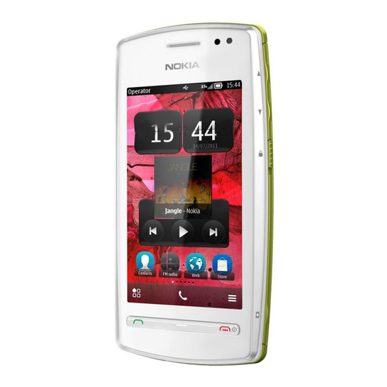
................................. 1–9 Table 2 Car................................1–10 Table 3 Data ................................ 1–11 Table 4 Power ..............................1–12 List of Figures Figure 1 View of RM-701............................1–5 Issue 1 COMPANY CONFIDENTIAL Page 1 – 3 Copyright © 2011 Nokia. All rights reserved. - Page 16 RM-701 General Information (This page left intentionally blank.) Page 1 – 4 COMPANY CONFIDENTIAL Issue 1 Copyright © 2011 Nokia. All rights reserved.
-
Page 17: Product Selection
107/64.2 kbit/s with GPRS. RM-701 has a large 3.2” (640 x 360 pixels) TFT colour display (active area 39.6 mm x 70.4 mm) with 16 million colors. It also has a 5 megapixel EDOF camera, 2 x digital zoom and an integrated LED flash. -
Page 18: Product Features And Sales Package
• Scene: automatic, user defined, portrait, landscape, night, night portrait • Colour tone: normal, sepia, B&W, vivid • Zoom (digital): 2x Edit • On device Photo editor (manual & automatic) Page 1 – 6 COMPANY CONFIDENTIAL Issue 1 Copyright © 2011 Nokia. All rights reserved. - Page 19 • 2 GB internal user memory • MicroSD card slot, support up to 32 GB • Nokia XpressTransfer – easy to transfer and organize photos and video between your device and a compatible PC • Nokia Lifeblog (mobile & PC) Music •...
- Page 20 • Nokia Push to Talk (PoC) Connectivity • Integrated GPS (A-GPS OMA SUPL) • Nokia Maps 3.0, including Friend Finder • WLAN - IEEE802.11 g/b/n with UPnP support • Micro USB interface with USB 2.0 high speed • Bluetooth wireless technology 2.0 + A2DP •...
-
Page 21: Product And Module List
Type Music headsets HS-45 HS-82 Wired headsets WH-102 WH-103 WH-201 WH-203 WH-204 WH-205 (inbox) WH-206 WH-207 WH-300 WH-500 WH-501 WH-600 WH-601 WH-701 WH-702 WH-800 WH-900 Issue 1 COMPANY CONFIDENTIAL Page 1 – 9 Copyright © 2011 Nokia. All rights reserved. -
Page 22: Table 2 Car
BH-602 BH-606 BH-607 BH-608 BH-609 BH-703 BH-803 BH-804 BH-806 BH-904 BH-905 Pocket speaker MD-10 Table 2 Car Enhancement Type Nokia universal mobile holder CR-114 CR-115 Page 1 – 10 COMPANY CONFIDENTIAL Issue 1 Copyright © 2011 Nokia. All rights reserved. -
Page 23: Table 3 Data
CA-157 CA-167 CA-179 (inbox) Video connectivity cable CA-75U MicroSD card MU-22, 1 GB MU-37, 2 GB MU-41, 4 GB MU-43, 8GB MU-44, 16GB MU-45 32GB Issue 1 COMPANY CONFIDENTIAL Page 1 – 11 Copyright © 2011 Nokia. All rights reserved. -
Page 24: Technical Specifications
WCDMA V (850): 869 - 894 MHz WCDMA IV (1700/2100): 2110 - 2155 MHz WCDMA II (1900): 1930 - 1990 MHz WCDMA I (2100): 2110 - 2170 MHz Page 1 – 12 COMPANY CONFIDENTIAL Issue 1 Copyright © 2011 Nokia. All rights reserved. - Page 25 WCDMA V (850): 108 WCDMA IV (1700/2100): 211 WCDMA II (1900): 289 WCDMA I (2100): 277 Channel spacing 200 kHz (WCDMA II, IV and V 100/200 kHz) Issue 1 COMPANY CONFIDENTIAL Page 1 – 13 Copyright © 2011 Nokia. All rights reserved.
-
Page 26: Battery Endurance
The HW module is not protected against water. Condensed or splashed water might cause malfunction. Any submersion of the phone will cause permanent damage. Long-term high humidity, with condensation, will cause permanent damage because of corrosion. Page 1 – 14 COMPANY CONFIDENTIAL Issue 1 Copyright © 2011 Nokia. All rights reserved. - Page 27 The standard for electrostatic discharge is IEC 61000-4-2, and this device fulfils level 4 requirements. RoHS This device uses RoHS compliant components and lead-free soldering process. Issue 1 COMPANY CONFIDENTIAL Page 1 – 15 Copyright © 2011 Nokia. All rights reserved.
- Page 28 RM-701 General Information (This page left intentionally blank.) Page 1 – 16 COMPANY CONFIDENTIAL Issue 1 Copyright © 2011 Nokia. All rights reserved.
- Page 29 Nokia Customer Care 2 — Service Tools and Service Concepts Issue 1 COMPANY CONFIDENTIAL Page 2 – 1 Copyright © 2011 Nokia. All rights reserved.
- Page 30 RM-701 Service Tools and Service Concepts (This page left intentionally blank.) Page 2 – 2 COMPANY CONFIDENTIAL Issue 1 Copyright © 2011 Nokia. All rights reserved.
-
Page 31: Table Of Contents
Figure 6 BB/RF tuning concept with MJ-300 and SS-227................2–17 Figure 7 Bluetooth testing concept with SB-6 ....................2–18 Figure 8 WLAN functionality testing concept with SB-7................. 2–19 Issue 1 COMPANY CONFIDENTIAL Page 2 – 3 Copyright © 2011 Nokia. All rights reserved. - Page 32 RM-701 Service Tools and Service Concepts (This page left intentionally blank.) Page 2 – 4 COMPANY CONFIDENTIAL Issue 1 Copyright © 2011 Nokia. All rights reserved.
-
Page 33: Service Tools
The table below gives a short overview of service devices that can be used for testing, error analysis, and repair of product RM-701. For the correct use of the service devices, and the best effort of workbench setup, please refer to various concepts. - Page 34 4 Connect an FBUS cable (if necessary). 5 Start Phoenix service software. Note: Phoenix enables CU-4 regulators via USB when it is started. Reconnecting the power supply requires a Phoenix restart. Page 2 – 6 COMPANY CONFIDENTIAL Issue 1 Copyright © 2011 Nokia. All rights reserved.
-
Page 35: Fps-21
In order to access the SD memory card slots inside FPS-21, the prommer needs to be opened by removing the front panel, rear panel and heatsink from the prommer body. Issue 1 COMPANY CONFIDENTIAL Page 2 – 7 Copyright © 2011 Nokia. All rights reserved. - Page 36 PK-1 is meant for use with a PC that does not have a series interface. To use this USB dongle for security service functions please register the dongle in the same way as the PKD-1 series dongle. Page 2 – 8 COMPANY CONFIDENTIAL Issue 1 Copyright © 2011 Nokia. All rights reserved.
- Page 37 Place the phone on coordinates "E-1" for testing. SRT-6 Opening tool SRT-6 is used to open phone covers. Note: The SRT-6 is included in the Nokia Standard Toolkit. Issue 1 COMPANY CONFIDENTIAL Page 2 – 9 Copyright © 2011 Nokia. All rights reserved.
- Page 38 • multiplexing between USB and FBUS media, controlled by VUSB SS-88 Camera removal tool The camera removal tool SS-88 is used to remove/attach the camera module from/to the camera socket of the phone PWB. Page 2 – 10 COMPANY CONFIDENTIAL Issue 1 Copyright © 2011 Nokia. All rights reserved.
-
Page 39: Cables
The table below gives a short overview of service devices that can be used for testing, error analysis, and repair of product RM-701. For the correct use of the service devices, and the best effort of workbench setup, please refer to various concepts. -
Page 40: Ca-31D
The MBUS cable DAU-9S has a modular connector and is used, for example, between the PC's serial port and module jigs, flash adapters or docking station adapters. Note: Docking station adapters valid for DCT4 products. Page 2 – 12 COMPANY CONFIDENTIAL Issue 1 Copyright © 2011 Nokia. All rights reserved. -
Page 41: Service Concepts
Attenuation for: • GSM850/900: 0.3+-0.1 dB • GSM1800/1900: 0.5+-0.1 dB • WCDMA/WLAN: 0.6+-0.1dB Service concepts POS (Point of Sale) flash concept Figure 2 POS flash concept Issue 1 COMPANY CONFIDENTIAL Page 2 – 13 Copyright © 2011 Nokia. All rights reserved. -
Page 42: Basic Flash Concept - Back End
Type Description Product specific devices SD-63 Care dummy battery Other devices PK-1 SW security device PC with Phoenix service software Cables CA-101 Micro USB cable Page 2 – 14 COMPANY CONFIDENTIAL Issue 1 Copyright © 2011 Nokia. All rights reserved. -
Page 43: Level 3 Concept For Flashing, Certificate Restore And Product Code Change
SW security device SX-4 Smart card (for DCT-4 generation mobile device programming) PC with Phoenix service software Cables CA-101 Micro USB cable CA-89DS Service cable Issue 1 COMPANY CONFIDENTIAL Page 2 – 15 Copyright © 2011 Nokia. All rights reserved. -
Page 44: Bb5 Usb Flash Concept With
SW security device SX-4 Smart card PC with service software Cables CA-101 Micro USB cable CA-89DS Service cable CA-99PS Adapter PCS-1 Power cable USB cable Page 2 – 16 COMPANY CONFIDENTIAL Issue 1 Copyright © 2011 Nokia. All rights reserved. -
Page 45: Bb/Rf Tuning Concept With Mj-300 And Ss-227.......................................................................................... Bluetooth Testing Concept With
Smart card PC with service software Measurement equipment Cables CA-101 Micro USB cable CA-89DS Service cable PCS-1 DC power cable XRS-6 RF cable USB cable Issue 1 COMPANY CONFIDENTIAL Page 2 – 17 Copyright © 2011 Nokia. All rights reserved. - Page 46 Battery Other devices PK-1 SW security device SX-4 Smart card SB-6 Bluetooth test and interface box Smart card reader PC with Phoenix service software Cables Page 2 – 18 COMPANY CONFIDENTIAL Issue 1 Copyright © 2011 Nokia. All rights reserved.
-
Page 47: Wlan Functionality Testing Concept With Sb-7
Product specific tools BL-4J Battery Other tools SX-4 Smart card PK-1 SW Security device Note: PK-1 can be used instead of PKD-1. Cables CA-101 Micro USB cable Issue 1 COMPANY CONFIDENTIAL Page 2 – 19 Copyright © 2011 Nokia. All rights reserved. - Page 48 RM-701 Service Tools and Service Concepts (This page left intentionally blank.) Page 2 – 20 COMPANY CONFIDENTIAL Issue 1 Copyright © 2011 Nokia. All rights reserved.
- Page 49 Nokia Customer Care 3 — BB Troubleshooting and Manual Tuning Guide Issue 1 COMPANY CONFIDENTIAL Page 3 – 1 Copyright © 2011 Nokia. All rights reserved.
- Page 50 RM-701 BB Troubleshooting and Manual Tuning Guide (This page left intentionally blank.) Page 3 – 2 COMPANY CONFIDENTIAL Issue 1 Copyright © 2011 Nokia. All rights reserved.
-
Page 51: Table 1 Audio
........................3–41 IHF troubleshooting ..........................3–41 Microphone troubleshooting ........................3–43 Vibra troubleshooting........................... 3–44 Connectivity module troubleshooting ......................3–44 Introduction to connectivity module troubleshooting ................3–44 Issue 1 COMPANY CONFIDENTIAL Page 3 – 3 Copyright © 2011 Nokia. All rights reserved. - Page 52 Figure 15 Connectivity antennas bottom view ....................3–46 Figure 16 Connectivity module's component layout, bottom side ............... 3–47 Figure 17 Bluetooth and FM radio self tests in Phoenix................. 3–51 Page 3 – 4 COMPANY CONFIDENTIAL Issue 1 Copyright © 2011 Nokia. All rights reserved.
- Page 53 Figure 23 GPS IO tests ............................3–68 Figure 24 GPS RTC oscillator test........................3–69 Figure 25 GPS ME oscillator test ........................3–70 Figure 26 GPS SNR test ............................3–71 Issue 1 COMPANY CONFIDENTIAL Page 3 – 5 Copyright © 2011 Nokia. All rights reserved.
- Page 54 RM-701 BB Troubleshooting and Manual Tuning Guide (This page left intentionally blank.) Page 3 – 6 COMPANY CONFIDENTIAL Issue 1 Copyright © 2011 Nokia. All rights reserved.
-
Page 55: Baseband Main Troubleshooting
Always start the troubleshooting procedure by running the Phoenix self tests. If a test fails, please follow the Dead or jammed device diagrams below. If the phone is dead and you cannot perform the self tests, go to troubleshooting . Issue 1 COMPANY CONFIDENTIAL Page 3 – 7 Copyright © 2011 Nokia. All rights reserved. - Page 56 RM-701 BB Troubleshooting and Manual Tuning Guide Troubleshooting flow - Page 1 of 3 Page 3 – 8 COMPANY CONFIDENTIAL Issue 1 Copyright © 2011 Nokia. All rights reserved.
- Page 57 RM-701 BB Troubleshooting and Manual Tuning Guide Troubleshooting flow - Page 2 of 3 Issue 1 COMPANY CONFIDENTIAL Page 3 – 9 Copyright © 2011 Nokia. All rights reserved.
- Page 58 RM-701 BB Troubleshooting and Manual Tuning Guide Troubleshooting flow - Page 3 of 3 Page 3 – 10 COMPANY CONFIDENTIAL Issue 1 Copyright © 2011 Nokia. All rights reserved.
-
Page 59: Power And Charging Troubleshooting
RM-701 BB Troubleshooting and Manual Tuning Guide Power and charging troubleshooting Backup battery troubleshooting Troubleshooting flow Issue 1 COMPANY CONFIDENTIAL Page 3 – 11 Copyright © 2011 Nokia. All rights reserved. -
Page 60: General Power Checking Troubleshooting
RM-701 BB Troubleshooting and Manual Tuning Guide General power checking troubleshooting Troubleshooting flow Page 3 – 12 COMPANY CONFIDENTIAL Issue 1 Copyright © 2011 Nokia. All rights reserved. -
Page 61: Dead Or Jammed Device Troubleshooting
RM-701 BB Troubleshooting and Manual Tuning Guide Dead or jammed device troubleshooting Troubleshooting flow Issue 1 COMPANY CONFIDENTIAL Page 3 – 13 Copyright © 2011 Nokia. All rights reserved. -
Page 62: Dynamo Charging Troubleshooting
RM-701 BB Troubleshooting and Manual Tuning Guide Dynamo charging troubleshooting Troubleshooting flow Page 3 – 14 COMPANY CONFIDENTIAL Issue 1 Copyright © 2011 Nokia. All rights reserved. -
Page 63: Usb Charging Troubleshooting
RM-701 BB Troubleshooting and Manual Tuning Guide USB charging troubleshooting Troubleshooting flow Issue 1 COMPANY CONFIDENTIAL Page 3 – 15 Copyright © 2011 Nokia. All rights reserved. -
Page 64: Interface Troubleshooting
RM-701 BB Troubleshooting and Manual Tuning Guide Interface troubleshooting USB flashing fault troubleshooting Troubleshooting flow Page 3 – 16 COMPANY CONFIDENTIAL Issue 1 Copyright © 2011 Nokia. All rights reserved. -
Page 65: Usb Data Interface Troubleshooting
RM-701 BB Troubleshooting and Manual Tuning Guide USB data interface troubleshooting Troubleshooting flow Issue 1 COMPANY CONFIDENTIAL Page 3 – 17 Copyright © 2011 Nokia. All rights reserved. -
Page 66: Sim Card Troubleshooting
RM-701 BB Troubleshooting and Manual Tuning Guide SIM card troubleshooting Troubleshooting flow Page 3 – 18 COMPANY CONFIDENTIAL Issue 1 Copyright © 2011 Nokia. All rights reserved. - Page 67 RM-701 BB Troubleshooting and Manual Tuning Guide Issue 1 COMPANY CONFIDENTIAL Page 3 – 19 Copyright © 2011 Nokia. All rights reserved.
-
Page 68: Microsd Card Troubleshooting
The following references on the PWB help in the effective debugging and troubleshooting of IVE. Sr. No Reference Description B1400 19.2MHz Crystal D1400 IVE/BCM2763A IC The following test points on the PWB help in the effective debugging and troubleshooting. Page 3 – 20 COMPANY CONFIDENTIAL Issue 1 Copyright © 2011 Nokia. All rights reserved. -
Page 69: Ive Troubleshooting
Sr. No Reference Description R1419 DAC termination resistor. Resistor value 15 OHMS. D1400 BCM2763A IC N2001 Analog switch L2005 Ferrite bead on the CVBS signal Issue 1 COMPANY CONFIDENTIAL Page 3 – 21 Copyright © 2011 Nokia. All rights reserved. -
Page 70: Sdtv Out Troubleshooting
The first step is to verify with a working display that the fault is not on the display module itself. The display module cannot be repaired. Note: Always use the display with the phone's window while checking the display's visual functionality. Page 3 – 22 COMPANY CONFIDENTIAL Issue 1 Copyright © 2011 Nokia. All rights reserved. - Page 71 (sometimes called blinking defects) exhibit temporal variations not related to any steady-state video input. Temporal sub-pixel defects may be intermittent, exhibit a sudden change of state, or be flickering. Issue 1 COMPANY CONFIDENTIAL Page 3 – 23 Copyright © 2011 Nokia. All rights reserved.
-
Page 72: Introduction To Display Troubleshooting
The following test points on the PWB help in the effective debugging and troubleshooting. Sr. No Signal name Measuring point Description L1600/C1600 1.8V supply to display VAUX1 C1602 VAUX1 supply to display Page 3 – 24 COMPANY CONFIDENTIAL Issue 1 Copyright © 2011 Nokia. All rights reserved. -
Page 73: Display Fault Troubleshooting
RM-701 BB Troubleshooting and Manual Tuning Guide Display fault troubleshooting Troubleshooting flow Issue 1 COMPANY CONFIDENTIAL Page 3 – 25 Copyright © 2011 Nokia. All rights reserved. -
Page 74: Touch Panel Troubleshooting
RM-701 BB Troubleshooting and Manual Tuning Guide Touch panel troubleshooting Troubleshooting flow Page 3 – 26 COMPANY CONFIDENTIAL Issue 1 Copyright © 2011 Nokia. All rights reserved. -
Page 75: Illumination Troubleshooting
RM-701 BB Troubleshooting and Manual Tuning Guide Illumination troubleshooting Charging illumination troubleshooting Troubleshooting flow Issue 1 COMPANY CONFIDENTIAL Page 3 – 27 Copyright © 2011 Nokia. All rights reserved. -
Page 76: Keyboard Backlight Troubleshooting
RM-701 BB Troubleshooting and Manual Tuning Guide Keyboard backlight troubleshooting Troubleshooting flow Page 3 – 28 COMPANY CONFIDENTIAL Issue 1 Copyright © 2011 Nokia. All rights reserved. -
Page 77: Keyboard Troubleshooting
Change the sensor and retest. Error details can be identified from Detailed Result. The last 3 bytes (in hexadecimal form) indicate the difference between the above mentioned two measurements for Issue 1 COMPANY CONFIDENTIAL Page 3 – 29 Copyright © 2011 Nokia. All rights reserved. -
Page 78: Magnetometer Troubleshooting
The 3rd byte in Detailed Result is a key to more accurate data, as seen in the figure. The Detailed Result information is important when communicating with the R&D regarding magnetometer failures. Page 3 – 30 COMPANY CONFIDENTIAL Issue 1 Copyright © 2011 Nokia. All rights reserved. -
Page 79: Dipro Technical Description And Troubleshooting
If the self test result is 'Minor', a pop-up window will open and the error can be identified from Detailed Result (see the following figure). Issue 1 COMPANY CONFIDENTIAL Page 3 – 31 Copyright © 2011 Nokia. All rights reserved. -
Page 80: Als Functionality Check And Calibration
If the diagnostics PC is equipped with a PC speaker, a short beep can be heard if the 'Sensor state' is read 'ON'. The sensor state will of course change accordingly. Page 3 – 32 COMPANY CONFIDENTIAL Issue 1 Copyright © 2011 Nokia. All rights reserved. -
Page 81: Audio Troubleshooting
Audio can be tested using the Phoenix audio routings option. Three different audio loop paths can be activated: • External headset mic to earpiece • External headset mic to IHF mono • Internal digital microphone to headset Issue 1 COMPANY CONFIDENTIAL Page 3 – 33 Copyright © 2011 Nokia. All rights reserved. - Page 82 IHF L4857 & mono L4858 Internal Acoustical HS_L & GND 94 dBSPL digital Input, 1kHz HS_R & GND microphon sine wave e to headset Page 3 – 34 COMPANY CONFIDENTIAL Issue 1 Copyright © 2011 Nokia. All rights reserved.
-
Page 83: External Earpiece Troubleshooting
RM-701 BB Troubleshooting and Manual Tuning Guide External earpiece troubleshooting Troubleshooting flow Issue 1 COMPANY CONFIDENTIAL Page 3 – 35 Copyright © 2011 Nokia. All rights reserved. -
Page 84: External Microphone Troubleshooting
RM-701 BB Troubleshooting and Manual Tuning Guide External microphone troubleshooting Troubleshooting flow Page 3 – 36 COMPANY CONFIDENTIAL Issue 1 Copyright © 2011 Nokia. All rights reserved. -
Page 85: Internal Earpiece Troubleshooting
RM-701 BB Troubleshooting and Manual Tuning Guide Internal earpiece troubleshooting Troubleshooting flow Issue 1 COMPANY CONFIDENTIAL Page 3 – 37 Copyright © 2011 Nokia. All rights reserved. -
Page 86: Internal Handsfree (Ihf) Troubleshooting
RM-701 BB Troubleshooting and Manual Tuning Guide Internal handsfree (IHF) troubleshooting Troubleshooting flow Page 3 – 38 COMPANY CONFIDENTIAL Issue 1 Copyright © 2011 Nokia. All rights reserved. -
Page 87: Internal Microphone Troubleshooting
RM-701 BB Troubleshooting and Manual Tuning Guide Internal microphone troubleshooting Troubleshooting flow Issue 1 COMPANY CONFIDENTIAL Page 3 – 39 Copyright © 2011 Nokia. All rights reserved. -
Page 88: Acoustics Troubleshooting
The phone should be dry and clean, and no objects must be located in such a way that they close any of the holes. Page 3 – 40 COMPANY CONFIDENTIAL Issue 1 Copyright © 2011 Nokia. All rights reserved. -
Page 89: Earpiece Troubleshooting
RM-701 BB Troubleshooting and Manual Tuning Guide Earpiece troubleshooting Troubleshooting flow Issue 1 COMPANY CONFIDENTIAL Page 3 – 41 Copyright © 2011 Nokia. All rights reserved. -
Page 90: Ihf Troubleshooting
RM-701 BB Troubleshooting and Manual Tuning Guide IHF troubleshooting Troubleshooting flow Page 3 – 42 COMPANY CONFIDENTIAL Issue 1 Copyright © 2011 Nokia. All rights reserved. -
Page 91: Microphone Troubleshooting
RM-701 BB Troubleshooting and Manual Tuning Guide Microphone troubleshooting Troubleshooting flow Issue 1 COMPANY CONFIDENTIAL Page 3 – 43 Copyright © 2011 Nokia. All rights reserved. -
Page 92: Vibra Troubleshooting
SMPS supplies the whole BOB1.0M-b solution from the phone battery supply, VBAT, apart from VIO which is needed for interface signal reference levels. The following figure shows a top level block diagram of the BOB1.0M-b module. Page 3 – 44 COMPANY CONFIDENTIAL Issue 1 Copyright © 2011 Nokia. All rights reserved. - Page 93 IHF (if internal FM antenna is used) through the BB ASIC shared by the phone audio functions. The antenna positions are presented in the following figure. Issue 1 COMPANY CONFIDENTIAL Page 3 – 45 Copyright © 2011 Nokia. All rights reserved.
- Page 94 RM-701 BB Troubleshooting and Manual Tuning Guide Figure 14 Connectivity antennas top view Figure 15 Connectivity antennas bottom view Page 3 – 46 COMPANY CONFIDENTIAL Issue 1 Copyright © 2011 Nokia. All rights reserved.
-
Page 95: Bluetooth/Fm Radio And Wlan Troubleshooting
Unable to switch on Bluetooth on Open circuit solder joints or Replacement of BOB module phone user interface component failure of BOB module or SMD components Issue 1 COMPANY CONFIDENTIAL Page 3 – 47 Copyright © 2011 Nokia. All rights reserved. - Page 96 FM radio aerial (for audio example, FM aerial routing inside car is very well screened or greater than 3 metre distance between the phone and FM radio) Page 3 – 48 COMPANY CONFIDENTIAL Issue 1 Copyright © 2011 Nokia. All rights reserved.
-
Page 97: Introduction To Wlan Troubleshooting
Unable to switch on WLAN on Open circuit solder joints or Replacement of BOB module phone user interface component failure of BOB or Host module Issue 1 COMPANY CONFIDENTIAL Page 3 – 49 Copyright © 2011 Nokia. All rights reserved. -
Page 98: Bluetooth And Fm Radio Self Tests In Phoenix
Bluetooth and FM radio self tests in Phoenix Prerequisites A flash adapter (or phone data cable) connected to a PC with Phoenix service software is required. Page 3 – 50 COMPANY CONFIDENTIAL Issue 1 Copyright © 2011 Nokia. All rights reserved. -
Page 99: Wlan Self Test In Phoenix
Phoenix service software. 2. Start 3. Choose File → Scan Product. 4. From the Mode drop-down menu, set mode to Local. 5. Choose Testing → Self Tests. Issue 1 COMPANY CONFIDENTIAL Page 3 – 51 Copyright © 2011 Nokia. All rights reserved. -
Page 100: Bluetooth Ber Test In Phoenix
5. Locate the BT-box serial number (12 digits) found in the type label on the back of the JBT-9, or SB-6 Bluetooth test box. LOCALS window, write the 12-digit serial number on the Counterpart BT Device 6. In the Bluetooth Address line. Page 3 – 52 COMPANY CONFIDENTIAL Issue 1 Copyright © 2011 Nokia. All rights reserved. -
Page 101: Fmrx Radio Receiver Testing
3. Use Scroll button to autotune to the radio frequency. 4. Set volume to suitable level. 5. Check audio quality with a headset. 6. Remove the Nokia headset and repeat steps 3. and 4. Issue 1 COMPANY CONFIDENTIAL Page 3 – 53... -
Page 102: Wlan Tx And Rx Testing In Phoenix
WLAN TX. The results are displayed and logged in a result file, if initiated. Steps Place the phone in the flash adapter or connect data cable to phone. Phoenix service software. Start Choose File → Scan Product. Page 3 – 54 COMPANY CONFIDENTIAL Issue 1 Copyright © 2011 Nokia. All rights reserved. -
Page 103: Wlan Tx Bip Testing Procedure In Testing And Tuning Tool
No external measurement equipment is required as the calibration is completely handled internally. RF cable and adapter losses do not need to be taken into account while WLAN TX tuning is proceeded. Issue 1 COMPANY CONFIDENTIAL Page 3 – 55 Copyright © 2011 Nokia. All rights reserved. - Page 104 1. Make sure the phone is connected to the PC. Nokia Care Suite application. 2. Start 3. To open the application, double-click the Testing And Tuning Tool icon. Page 3 – 56 COMPANY CONFIDENTIAL Issue 1 Copyright © 2011 Nokia. All rights reserved.
- Page 105 4. If the application is able to find a connected phone, the following view will open: 5. Click on the RF Tuning button and select from the drop-down menu: Issue 1 COMPANY CONFIDENTIAL Page 3 – 57 Copyright © 2011 Nokia. All rights reserved.
- Page 106 7. If errors do happen, failed tuning/testing steps are marked with a red color and more detailed results are shown on the screen. Page 3 – 58 COMPANY CONFIDENTIAL Issue 1 Copyright © 2011 Nokia. All rights reserved.
-
Page 107: Bluetooth Troubleshooting
RM-701 BB Troubleshooting and Manual Tuning Guide Bluetooth troubleshooting Symptoms and diagnosis Troubleshooting flow Issue 1 COMPANY CONFIDENTIAL Page 3 – 59 Copyright © 2011 Nokia. All rights reserved. -
Page 108: Fmrx Receiver Troubleshooting
RM-701 BB Troubleshooting and Manual Tuning Guide FMRX receiver troubleshooting Troubleshooting flow Page 3 – 60 COMPANY CONFIDENTIAL Issue 1 Copyright © 2011 Nokia. All rights reserved. -
Page 109: Fm Tx Troubleshooting
• Check the surrounding components and ensure correct placement on the PWB and that there is no visual damage. Check that there are no missing components. Issue 1 COMPANY CONFIDENTIAL Page 3 – 61 Copyright © 2011 Nokia. All rights reserved. -
Page 110: Fmtx Troubleshooting
RM-701 BB Troubleshooting and Manual Tuning Guide FMTX troubleshooting Troubleshooting flow Page 3 – 62 COMPANY CONFIDENTIAL Issue 1 Copyright © 2011 Nokia. All rights reserved. -
Page 111: Wlan Troubleshooting
The GPS components are located on the bottom side of the PWB. Satellite signals are picked up by the GPS antenna and the signal is then processed by the BCM4751 receiver ASIC. Issue 1 COMPANY CONFIDENTIAL Page 3 – 63 Copyright © 2011 Nokia. All rights reserved. -
Page 112: Gps Rf Test Points
CW test. E6203 = GPS Ant J6210 = GPS production antenna test point J6211 = GPS production Ant Gnd Figure 19 GPS antenna pad (bottom side) Page 3 – 64 COMPANY CONFIDENTIAL Issue 1 Copyright © 2011 Nokia. All rights reserved. -
Page 113: Gps Settings For Phoenix
7. In the • ST_GPS_TEST 8. To run the test, click Start. Self Tests: Basic functionality of GPS ASIC and I2C, HOST_REQ, and RESET_ENA pin connections. Issue 1 COMPANY CONFIDENTIAL Page 3 – 65 Copyright © 2011 Nokia. All rights reserved. -
Page 114: Sw Checksum Tests
These tests can also be run separately by selecting just one of the two tests. 8. Click Start test. Results Results window. The result of the tests is shown in the Page 3 – 66 COMPANY CONFIDENTIAL Issue 1 Copyright © 2011 Nokia. All rights reserved. -
Page 115: Gps Io Tests
NPE equivalent pin number : 4,2,3,9 • Procedure : 1,2,4,8 10. Click Start test. Results Results window. The result of the tests is shown in the Issue 1 COMPANY CONFIDENTIAL Page 3 – 67 Copyright © 2011 Nokia. All rights reserved. -
Page 116: Gps Rtc Oscillator Test
RTC oscillator offset limit (Hz) : 1.5 10. Click Start test. Results The Offset result will be returned and should be within the limits of +-1.5 Hz. Page 3 – 68 COMPANY CONFIDENTIAL Issue 1 Copyright © 2011 Nokia. All rights reserved. -
Page 117: Gps Me Oscillator Test
ME oscillator offset limit (Hz) : 194 10. Click Start test. Results The Offset result will be returned and should be within the limits of +-194 Hz. Issue 1 COMPANY CONFIDENTIAL Page 3 – 69 Copyright © 2011 Nokia. All rights reserved. -
Page 118: Gps Snr Test
Signal level offset limit (dBHz) : (Galvanic) 5 or (Radiated) 10 11. Click Start test. Results For Pin = -115 dBm and neglible other losses, the expected result ranges are: Page 3 – 70 COMPANY CONFIDENTIAL Issue 1 Copyright © 2011 Nokia. All rights reserved. - Page 119 RM-701 BB Troubleshooting and Manual Tuning Guide • Galvanic: 52 – 62 dBHz • Radiated: 47 – 67 dBHz Figure 26 GPS SNR test Issue 1 COMPANY CONFIDENTIAL Page 3 – 71 Copyright © 2011 Nokia. All rights reserved.
-
Page 120: Gps Failure Troubleshooting
RM-701 BB Troubleshooting and Manual Tuning Guide GPS failure troubleshooting Troubleshooting flow Page 3 – 72 COMPANY CONFIDENTIAL Issue 1 Copyright © 2011 Nokia. All rights reserved. -
Page 121: Nfc Troubleshooting
RM-701 BB Troubleshooting and Manual Tuning Guide NFC troubleshooting Troubleshooting flow Issue 1 COMPANY CONFIDENTIAL Page 3 – 73 Copyright © 2011 Nokia. All rights reserved. -
Page 122: Baseband Manual Tuning Guide
• When certificate restoring for BB 5 products or IMEI rebuild for DCT-4 products is performed, existing data from Nokia System is programmed in the phone. The phone will be in the same condition as it was when it left the factory for the first time. - Page 123 5. Product code shown on the UI does not matter, because during restoring it will be replaced by the product code which is the latest one stored in Nokia system. 6. It is recommended to perform "Restore"-function without selecting "Flash Product"-option to avoid possible SW downgrade which causes the phone to die.
- Page 124 BB Troubleshooting and Manual Tuning Guide 7. Information from phone and Smart Card are read and connection to Tucson server is established. 8. Information from Nokia system is retreived and programmed in the phone. Page 3 – 76 COMPANY CONFIDENTIAL Issue 1 Copyright ©...
-
Page 125: Product Code Change
Nokia System, and programmed in the phone. • After successful change, phone specific information in Nokia systems will match the new variant, and it can be used for e.g. certificate restoring. If you perform several product code changes, Nokia system will always be up to date with the latest successful event. - Page 126 Select product code of new variant from list. If the product code you want is not shown, please install correct data package including the variant. Select “OK” and “SWAP”. Page 3 – 78 COMPANY CONFIDENTIAL Issue 1 Copyright © 2011 Nokia. All rights reserved.
- Page 127 BB Troubleshooting and Manual Tuning Guide Information from phone is read and connection to Tucson server is established. If “Flash Product” – option was selected, phone SW is programmed. Issue 1 COMPANY CONFIDENTIAL Page 3 – 79 Copyright © 2011 Nokia. All rights reserved.
- Page 128 RM-701 BB Troubleshooting and Manual Tuning Guide New data retrieved from Nokia system is programmed in the phone. Confirmation about successful event is sent to Nokia system. Page 3 – 80 COMPANY CONFIDENTIAL Issue 1 Copyright © 2011 Nokia. All rights reserved.
-
Page 129: Energy Management Calibration
Energy Management (EM) calibration is performed to calibrate the setting (gain and offset) of AD converters in several channels (that is, battery voltage, BSI, battery current) to get an accurate AD conversion result. Hardware setup: Issue 1 COMPANY CONFIDENTIAL Page 3 – 81 Copyright © 2011 Nokia. All rights reserved. - Page 130 Write and/or repeat the procedure again. Energy Management Calibration window. 10. To end the procedure, close the Page 3 – 82 COMPANY CONFIDENTIAL Issue 1 Copyright © 2011 Nokia. All rights reserved.
- Page 131 Nokia Customer Care 4 — Cellular RF troubleshooting Issue 1 COMPANY CONFIDENTIAL Page 4 – 1 Copyright © 2011 Nokia. All rights reserved.
- Page 132 RM-701 Cellular RF troubleshooting (This page left intentionally blank.) Page 4 – 2 COMPANY CONFIDENTIAL Issue 1 Copyright © 2011 Nokia. All rights reserved.
-
Page 133: Table
Self test troubleshooting..........................4–10 Troubleshooting with RF Self tests......................4–10 RF tuning and testing ............................4–12 RF auto tuning and testing with Nokia Care Suite..................4–12 RF auto tuning procedure ..........................4–12 Automatic RF testing with Nokia Care Suite....................4–17 Troubleshooting with Testing And Tuning Tool .................. - Page 134 RM-701 Cellular RF troubleshooting (This page left intentionally blank.) Page 4 – 4 COMPANY CONFIDENTIAL Issue 1 Copyright © 2011 Nokia. All rights reserved.
-
Page 135: General Instructions For Cellular Rf Troubleshooting
Level of repair The scope of this guideline is to verify functionality of the cellular RF block as well as possible without removing RF shields. Issue 1 COMPANY CONFIDENTIAL Page 4 – 5 Copyright © 2011 Nokia. All rights reserved. -
Page 136: Cellular Rf Key Components
Linko RF has separate RF shielding cans for: • Nitro N7509 + surroundings (Shield A) • Ukko PA N7510 + QuBBE Z7513 (Shield B) • Älli N7512 + surroundings (Shield C) Page 4 – 6 COMPANY CONFIDENTIAL Issue 1 Copyright © 2011 Nokia. All rights reserved. -
Page 137: Cellular Rf Main Troubleshooting
All RF shields are solid and should not be opened in service centers. Cellular RF main troubleshooting Cellular RF main troubleshooting Context Always start the cellular RF related troubleshooting procedure by following the diagram below. Issue 1 COMPANY CONFIDENTIAL Page 4 – 7 Copyright © 2011 Nokia. All rights reserved. - Page 138 RM-701 Cellular RF troubleshooting Troubleshooting flow — Page 1 of 2 Page 4 – 8 COMPANY CONFIDENTIAL Issue 1 Copyright © 2011 Nokia. All rights reserved.
- Page 139 RM-701 Cellular RF troubleshooting Troubleshooting flow — Page 2 of 2 Issue 1 COMPANY CONFIDENTIAL Page 4 – 9 Copyright © 2011 Nokia. All rights reserved.
-
Page 140: Self Test Troubleshooting
• Tests the basic functionality of the WCDMA transmitter. To get the best out of these instructions you need to have the valid schematics at hand. Page 4 – 10 COMPANY CONFIDENTIAL Issue 1 Copyright © 2011 Nokia. All rights reserved. - Page 141 RM-701 Cellular RF troubleshooting Troubleshooting flow Issue 1 COMPANY CONFIDENTIAL Page 4 – 11 Copyright © 2011 Nokia. All rights reserved.
-
Page 142: Rf Tuning And Testing
RF components are changed or memory (D3000) is corrupted. RM-701 can be tuned automatically. Auto tuning is designed to align the phone's RF part easily and faster. It performs calibrations, tunings and measurements of RX and TX. The results are displayed and logged in a result file, if initiated. - Page 143 RM-701 Cellular RF troubleshooting Nokia Care Suite application. The following window opens: Start Nokia Care Suite version. Note: The window appearance may differ depending on the Fuse, Multi Software Updater, Product Support Tool For Store and Testing And Tuning Tool Note: are Care Suite add-on applications.
- Page 144 To open the application, double-click Testing And Tuning Tool icon. If the application is able to find a connected phone, the following view will open: Nokia Care Suite and Testing And Tuning Note: The window appearance may differ depending on the Tool versions Click on the RF Tuning button.
- Page 145 Select Cellular RF Tunings and Tests from the drop-down menu. Select the RF cable used (and possible RF splitter / RF shield box) from the drop-down menu. CA-128RS attenuation values are always taken automatically into account when RM-701 product is connected to Nokia Care Suite tool.
- Page 146 14 If errors do happen, failed tuning/testing steps are marked with a red color and more detailed results are shown on the screen. An example fail case is shown below: Page 4 – 16 COMPANY CONFIDENTIAL Issue 1 Copyright © 2011 Nokia. All rights reserved.
-
Page 147: Automatic Rf Testing With Nokia Care Suite
RM-701 Cellular RF troubleshooting Nokia Care Suite and Testing And Tuning Note: The window appearance may differ depending on the Tool versions Automatic RF testing with Nokia Care Suite Testing And Tuning Tool add-on application can be used also for non-signalling RF tests. The automatic RF... -
Page 148: Troubleshooting With Testing And Tuning Tool
RM-701 Cellular RF troubleshooting Nokia Care Suite and Testing And Tuning Note: The window appearance may differ depending on the Tool versions. RF Testing selection does all the same measurements as RF Tuning , but does not perform any tunings. -
Page 149: Gsm Transmitter Activation
(for example CMU–200). Change power level (in “RF Controls” tool) and make sure the power reading follows accordingly. Issue 1 COMPANY CONFIDENTIAL Page 4 – 19 Copyright © 2011 Nokia. All rights reserved. - Page 150 RM-701 Cellular RF troubleshooting Page 4 – 20 COMPANY CONFIDENTIAL Issue 1 Copyright © 2011 Nokia. All rights reserved.
-
Page 151: Wcdma Transmitter Activation
Optional step (not needed if WCDMA TX activation only required): Check the basic TX parameters using a communication analyzer (for example CMU–200). Note: RM-701 WCDMA TX power classes: WCDMA I, II, IV, V and VIII class 3 (maximum output power +24 dBm). Issue 1 COMPANY CONFIDENTIAL Page 4 –... -
Page 152: Manual Receiver (Rx) Testing With Phoenix
For GSM RSSI measurements, see chapter measurements/GSM RSSI measurement . For a similar test in WCDMA mode, see chapter WCDMA RSSI measurement . Page 4 – 22 COMPANY CONFIDENTIAL Issue 1 Copyright © 2011 Nokia. All rights reserved. -
Page 153: Gsm Rx Chain Activation For Manual Measurements/Gsm Rssi Measurement
1. Set the phone to local mode. RX Control tool in Phoenix (Testing —> WCDMA —> RX Control) . 2. Activate 3. In the RX Control window, make the following settings: Issue 1 COMPANY CONFIDENTIAL Page 4 – 23 Copyright © 2011 Nokia. All rights reserved. -
Page 154: Wcdma Rssi Measurement
RX frequency 2140.0 MHz 1960.0 MHz 2132.4 MHz 881.6 MHz 942.4 MHz Signal generator 2141.0 MHz 1961.0 MHz 2133.4 MHz 882.6 MHz 943.4 MHz frequency Page 4 – 24 COMPANY CONFIDENTIAL Issue 1 Copyright © 2011 Nokia. All rights reserved. -
Page 155: Antenna
Antenna Antenna overview RM-701 has a GSM/WCDMA antenna located on the bottom of the phone. The GSM/WCDMA antenna has one feed connection and one ground connection. The connection from the phone PWB to the antenna module is implemented by spring contacts (2 pcs). - Page 156 The GPS, BT/WLAN and FM RX antennas are placed on the top of the phone/C-cover assembly and fed by pogo pins. Also the FM TX antenna can be found from the C-cover and it is connected to the PWB by two C-clips. Page 4 – 26 COMPANY CONFIDENTIAL Issue 1 Copyright © 2011 Nokia. All rights reserved.
- Page 157 RM-701 Cellular RF troubleshooting Figure 31 GPS, BT/WLAN, NFC, FM RX and FM TX antennas from the battery side Issue 1 COMPANY CONFIDENTIAL Page 4 – 27 Copyright © 2011 Nokia. All rights reserved.
-
Page 158: Antenna Troubleshooting
There are two antenna matching components (C7591 and L7597) on the PWB. Check that they are properly soldered. In case of damage, replace the component. Page 4 – 28 COMPANY CONFIDENTIAL Issue 1 Copyright © 2011 Nokia. All rights reserved. - Page 159 Check also that the GND pogo pins exist in the phone mechanics and take a proper contact to the PWB. Figure 35 GPS, BT/WLAN, FM RX and NFC antenna PWB feedings Issue 1 COMPANY CONFIDENTIAL Page 4 – 29 Copyright © 2011 Nokia. All rights reserved.
- Page 160 RM-701 Cellular RF troubleshooting Figure 36 FM TX antenna PWB contacts CWS antenna matching circuits Figure 37 NFC antenna matching schematic Page 4 – 30 COMPANY CONFIDENTIAL Issue 1 Copyright © 2011 Nokia. All rights reserved.
- Page 161 RM-701 Cellular RF troubleshooting Figure 38 NFC and FM RX antenna matching components Figure 39 FM RX antenna components (layout) Issue 1 COMPANY CONFIDENTIAL Page 4 – 31 Copyright © 2011 Nokia. All rights reserved.
- Page 162 RM-701 Cellular RF troubleshooting Figure 40 NFC antenna matching components (layout) Page 4 – 32 COMPANY CONFIDENTIAL Issue 1 Copyright © 2011 Nokia. All rights reserved.
- Page 163 RM-701 Cellular RF troubleshooting Figure 41 FM TX antenna matching component (layout) Figure 42 FM TX antenna matching component Issue 1 COMPANY CONFIDENTIAL Page 4 – 33 Copyright © 2011 Nokia. All rights reserved.
- Page 164 RM-701 Cellular RF troubleshooting Figure 43 FM RX-TX antenna matching schematic Page 4 – 34 COMPANY CONFIDENTIAL Issue 1 Copyright © 2011 Nokia. All rights reserved.
- Page 165 Nokia Customer Care 5 — Camera Module Troubleshooting Issue 1 COMPANY CONFIDENTIAL Page 5 – 1 Copyright © 2011 Nokia. All rights reserved.
- Page 166 RM-701 Camera Module Troubleshooting (This page left intentionally blank.) Page 5 – 2 COMPANY CONFIDENTIAL Issue 1 Copyright © 2011 Nokia. All rights reserved.
- Page 167 Figure 57 Enlargement of a hot pixel....................... 5–14 Figure 58 Light from the flash has reflected on particles in front of the camera ........5–14 Issue 1 COMPANY CONFIDENTIAL Page 5 – 3 Copyright © 2011 Nokia. All rights reserved.
- Page 168 RM-701 Camera Module Troubleshooting (This page left intentionally blank.) Page 5 – 4 COMPANY CONFIDENTIAL Issue 1 Copyright © 2011 Nokia. All rights reserved.
-
Page 169: Introduction To Camera Module Troubleshooting
Analogous to ISO speed in photographic film. Issue 1 COMPANY CONFIDENTIAL Page 5 – 5 Copyright © 2011 Nokia. All rights reserved. -
Page 170: The Effect Of Image Taking Conditions On Image Quality
The movement of camera or object sometimes cause blurring indoors or in dim lighting conditions because of long exposure time. This is normal; do not change the camera module. Page 5 – 6 COMPANY CONFIDENTIAL Issue 1 Copyright © 2011 Nokia. All rights reserved. - Page 171 In practice, this means that when taking an image indoors and having, for example, a window behind the object, the result is usually poor. This is normal behaviour; do not change the camera module. Issue 1 COMPANY CONFIDENTIAL Page 5 – 7 Copyright © 2011 Nokia. All rights reserved.
- Page 172 Generally this kind of reflections are common in all optical systems. This is normal behaviour; do not change the camera module. Page 5 – 8 COMPANY CONFIDENTIAL Issue 1 Copyright © 2011 Nokia. All rights reserved.
- Page 173 Figure 49 A lens reflection effect caused by sunshine Examples of good quality images Figure 50 Good image taken indoors Figure 51 Good image taken outdoors Issue 1 COMPANY CONFIDENTIAL Page 5 – 9 Copyright © 2011 Nokia. All rights reserved.
-
Page 174: Image Quality Analysis
However, it is possible that a larger particle disturbs the user, causing need for service. Figure 52 Effects of dust on optical path Page 5 – 10 COMPANY CONFIDENTIAL Issue 1 Copyright © 2011 Nokia. All rights reserved. -
Page 175: Testing Camera Image Sharpness
Any particles inside the cavity between the protection window and lens have most probably been trapped there in the assembly phase at a Nokia factory. Unauthorized disassembling of the product can also be the root of the problem. However, in most cases it should be possible to remove the particle(s) by using clean compressed air. -
Page 176: Effects Of Dirty Or Defective Camera Lens Protection Window
Figure 53 Image taken with clear protection window Figure 54 Image taken with greasy protection window Page 5 – 12 COMPANY CONFIDENTIAL Issue 1 Copyright © 2011 Nokia. All rights reserved. -
Page 177: Faulty Pixels In Images
This is normal behavior, do not change the camera. Issue 1 COMPANY CONFIDENTIAL Page 5 – 13 Copyright © 2011 Nokia. All rights reserved. -
Page 178: Flash Photography Problems
• Dust reflections. Dust or water drops in front of the flash unit may reflect strongly to the camera sensor. See the following figure. Figure 58 Light from the flash has reflected on particles in front of the camera Page 5 – 14 COMPANY CONFIDENTIAL Issue 1 Copyright © 2011 Nokia. All rights reserved. -
Page 179: Main (Back) Camera Troubleshooting Flowcharts
RM-701 Camera Module Troubleshooting Main (back) camera troubleshooting flowcharts No recognizable viewfinder image Troubleshooting flow Issue 1 COMPANY CONFIDENTIAL Page 5 – 15 Copyright © 2011 Nokia. All rights reserved. -
Page 180: Bad Image Quality Troubleshooting
RM-701 Camera Module Troubleshooting Bad image quality troubleshooting Troubleshooting flow Page 5 – 16 COMPANY CONFIDENTIAL Issue 1 Copyright © 2011 Nokia. All rights reserved. -
Page 181: Main Camera Troubleshooting
The following references on the PWB help in the effective debugging and troubleshooting of the main/ primary camera. Sr. No Reference Description X1476 Primary camera socket Troubleshooting flow Issue 1 COMPANY CONFIDENTIAL Page 5 – 17 Copyright © 2011 Nokia. All rights reserved. - Page 182 RM-701 Camera Module Troubleshooting (This page left intentionally blank.) Page 5 – 18 COMPANY CONFIDENTIAL Issue 1 Copyright © 2011 Nokia. All rights reserved.
- Page 183 Nokia Customer Care 6 — System Module Issue 1 COMPANY CONFIDENTIAL Page 6 – 1 Copyright © 2011 Nokia. All rights reserved.
- Page 184 RM-701 System Module (This page left intentionally blank.) Page 6 – 2 COMPANY CONFIDENTIAL Issue 1 Copyright © 2011 Nokia. All rights reserved.
- Page 185 6–30 Frequency mappings............................6–31 GSM850 frequencies ............................6–31 EGSM900 frequencies ............................ 6–32 GSM1800 frequencies............................ 6–32 GSM1900 frequencies............................ 6–34 WCDMA I (2100) Rx frequencies ........................6–35 Issue 1 COMPANY CONFIDENTIAL Page 6 – 3 Copyright © 2011 Nokia. All rights reserved.
- Page 186 Figure 78 Internal microphone diagram ......................6–27 Figure 79 Vibra diagram ............................ 6–28 Figure 80 AV connector............................6–28 Figure 81 Linko RF block diagram ........................6–29 Page 6 – 4 COMPANY CONFIDENTIAL Issue 1 Copyright © 2011 Nokia. All rights reserved.
-
Page 187: Introduction
X1600 RF connectors X7501 X7502 USB transceiver TUSB1211 D3300 MicroSD connector Toivo X3200 USB connector Micro USB-AB X3300 SIM connector Trap X2700 Imaging processor D1400 Issue 1 COMPANY CONFIDENTIAL Page 6 – 5 Copyright © 2011 Nokia. All rights reserved. - Page 188 N1105 Proximity and ALS sensor DiPro N1100 Dynamo charging circuit BQ24156 N3302 USB charging circuit BQ24153 N3301 Camera socket SMIA65 On-Board X1476 Key component placement Page 6 – 6 COMPANY CONFIDENTIAL Issue 1 Copyright © 2011 Nokia. All rights reserved.
- Page 189 RM-701 System Module Issue 1 COMPANY CONFIDENTIAL Page 6 – 7 Copyright © 2011 Nokia. All rights reserved.
- Page 190 RM-701 System Module System module block diagram Page 6 – 8 COMPANY CONFIDENTIAL Issue 1 Copyright © 2011 Nokia. All rights reserved.
-
Page 191: Energy Management
In the table below normal and extreme voltages are shown when a BL-4J battery is used. Table 9 Nominal voltages Voltage Voltage [V] Condition General Conditions Nominal voltage 3.700 Lower extreme voltage Issue 1 COMPANY CONFIDENTIAL Page 6 – 9 Copyright © 2011 Nokia. All rights reserved. -
Page 192: Power Key And System Power Up
SLEEP mode is entered only from PWR_ON mode with the aid of SW when the system’s activity is low. FLASHING FLASHING mode is for SW downloading. Page 6 – 10 COMPANY CONFIDENTIAL Issue 1 Copyright © 2011 Nokia. All rights reserved. -
Page 193: Power Distribution
RM-701 System Module Power distribution Issue 1 COMPANY CONFIDENTIAL Page 6 – 11 Copyright © 2011 Nokia. All rights reserved. -
Page 194: Clock Scheme
RM-701 System Module Clock scheme Page 6 – 12 COMPANY CONFIDENTIAL Issue 1 Copyright © 2011 Nokia. All rights reserved. -
Page 195: Sim Interface
IC. The phone uses BOB1.0M-b module that consists of a single chip transceiver WL1271, plus a separate RF front end (FE) device. The BOB1.0M-b release operates in the 2.4GHz (ISM) and the 76-108MHz FM bands. Issue 1 COMPANY CONFIDENTIAL Page 6 – 13 Copyright © 2011 Nokia. All rights reserved. - Page 196 The internal SMPS supplies the whole BOB1.0M-b solution from the phone battery supply, VBAT, apart from VIO, which is needed for interface signal reference levels. Page 6 – 14 COMPANY CONFIDENTIAL Issue 1 Copyright © 2011 Nokia. All rights reserved.
-
Page 197: Gps Interface
GPSCost5.0D operates in Multi-master mode and the REF clock is requested via AGPS_CLK_REQ signal connected to RAPU genio46. REFOUT_EXT2 single ended 38.4 MHz analog clock from Linko RF is provided to GPSCost5.0D. Issue 1 COMPANY CONFIDENTIAL Page 6 – 15 Copyright © 2011 Nokia. All rights reserved. -
Page 198: Nfc Interface
CMT RF circuitry. The system has an SWP connection to the SIM card for secure element purposes. The NFC secure element feature also requires a VSIM connection from the host to the NFC engine. Page 6 – 16 COMPANY CONFIDENTIAL Issue 1 Copyright © 2011 Nokia. All rights reserved. -
Page 199: Usb
The phone has an interface for USB (Universal Serial Bus). USB is a differential serial bus that provides a wired connectivity between a PC and peripheral devices, as in this case a mobile phone. Issue 1 COMPANY CONFIDENTIAL Page 6 – 17 Copyright © 2011 Nokia. All rights reserved. -
Page 200: Microusb Connector
Hot swap is supported, which means that USB devices may be plugged in and out at any time. MicroUSB connector This phone is provided with a specific connector for microUSB. Figure 66 MicroUSB connector Page 6 – 18 COMPANY CONFIDENTIAL Issue 1 Copyright © 2011 Nokia. All rights reserved. -
Page 201: Charger Interface
Whenever the user touches the touch screen, the controller raises an interrupt to RAPU which initiates I2C transactions to identify the locations the user touches on the display. Figure 68 Touch system block diagram Issue 1 COMPANY CONFIDENTIAL Page 6 – 19 Copyright © 2011 Nokia. All rights reserved. -
Page 202: Proximity Sensor And Ambient Light Sensor (Als)
• TFT DSI display • NTSC/PAL analog TV-out MeSSI-16 and CCP2-Tx are the key interfaces between RapuYama and BCM2763C. BCM2763C has in-build 256Mb stacked SDRAM. Page 6 – 20 COMPANY CONFIDENTIAL Issue 1 Copyright © 2011 Nokia. All rights reserved. -
Page 203: Display Module
For the Analog TV-out, video data is passed from the host to the BCM2763C over MeSSI-16 interface and BCM2763C sends it to the AV connector. Audio is routed separately by the host to the AV connector. Issue 1 COMPANY CONFIDENTIAL Page 6 – 21 Copyright © 2011 Nokia. All rights reserved. -
Page 204: Camera
There is no privacy indicator. Audio sound is used to indicate photo taking and video capture. Page 6 – 22 COMPANY CONFIDENTIAL Issue 1 Copyright © 2011 Nokia. All rights reserved. -
Page 205: Illumination
The 3D accelerometer (N1103) is connected to RAPU via two GENIOs (INT1=Genio12, INT2=Genio44) and I2C_0 bus. Supply voltages are VIO (1.8 V) and VAUX1 (2.8 V). Issue 1 COMPANY CONFIDENTIAL Page 6 – 23 Copyright © 2011 Nokia. All rights reserved. -
Page 206: Magnetometer
In the Maps application, the status of the magnetometer calibration is indicated by the compass color. Page 6 – 24 COMPANY CONFIDENTIAL Issue 1 Copyright © 2011 Nokia. All rights reserved. -
Page 207: Audio Concept
Audio HW architecture TPA6140 (N2000), BoostMono (N2150) along with mixed-signal ASIC Gazoo/Pearl provides the analogue audio output interfaces and RAPU provides the digital audio output interface support. Issue 1 COMPANY CONFIDENTIAL Page 6 – 25 Copyright © 2011 Nokia. All rights reserved. - Page 208 RM-701 System Module Figure 75 Audio system and AV connector block diagram Page 6 – 26 COMPANY CONFIDENTIAL Issue 1 Copyright © 2011 Nokia. All rights reserved.
-
Page 209: Internal Earpiece
The digital microphone used is Knopfler and it is connected to Rapu. DigiMic CLK is connected to Rapu Genio72 and DigiMic DATA is connected to Rapu Genio39. Figure 78 Internal microphone diagram Issue 1 COMPANY CONFIDENTIAL Page 6 – 27 Copyright © 2011 Nokia. All rights reserved. -
Page 210: External Earpiece And Microphone
Linko RF consists of the following key components: • Älli (Transceiver RF Asic) • Nitro (RF power management Asic) • Ukko PA • QuBBE (Front end module) Page 6 – 28 COMPANY CONFIDENTIAL Issue 1 Copyright © 2011 Nokia. All rights reserved. -
Page 211: Qubbe
• ADC: Programmable Sigma Delta Modulator topology ADC • RX Digital Front End (RXDFE): Contains for example digital filtering, DC offset compensation, wide/ narrowband power measurement blocks Issue 1 COMPANY CONFIDENTIAL Page 6 – 29 Copyright © 2011 Nokia. All rights reserved. -
Page 212: Synthesizer
In WCDMA and EDGE mode, the output power is tuned by output level of Älli. The supply voltage in WCDMA mode is adjusted in power levels to optimize the current consumption. Page 6 – 30 COMPANY CONFIDENTIAL Issue 1 Copyright © 2011 Nokia. All rights reserved. -
Page 213: Frequency Mappings
RM-701 System Module Frequency mappings GSM850 frequencies Issue 1 COMPANY CONFIDENTIAL Page 6 – 31 Copyright © 2011 Nokia. All rights reserved. -
Page 214: Egsm900 Frequencies
RM-701 System Module EGSM900 frequencies Page 6 – 32 COMPANY CONFIDENTIAL Issue 1 Copyright © 2011 Nokia. All rights reserved. -
Page 215: Gsm1800 Frequencies
RM-701 System Module GSM1800 frequencies Issue 1 COMPANY CONFIDENTIAL Page 6 – 33 Copyright © 2011 Nokia. All rights reserved. -
Page 216: Gsm1900 Frequencies
RM-701 System Module GSM1900 frequencies Page 6 – 34 COMPANY CONFIDENTIAL Issue 1 Copyright © 2011 Nokia. All rights reserved. -
Page 217: Wcdma I (2100) Rx Frequencies
RM-701 System Module WCDMA I (2100) Rx frequencies Issue 1 COMPANY CONFIDENTIAL Page 6 – 35 Copyright © 2011 Nokia. All rights reserved. - Page 218 RM-701 System Module WCDMA I (2100) Tx frequencies Page 6 – 36 COMPANY CONFIDENTIAL Issue 1 Copyright © 2011 Nokia. All rights reserved.
- Page 219 RM-701 System Module WCDMA II (1900) frequencies Issue 1 COMPANY CONFIDENTIAL Page 6 – 37 Copyright © 2011 Nokia. All rights reserved.
- Page 220 RM-701 System Module WCDMA IV (1700/2100) frequencies Page 6 – 38 COMPANY CONFIDENTIAL Issue 1 Copyright © 2011 Nokia. All rights reserved.
- Page 221 RM-701 System Module WCDMA V (850) frequencies Issue 1 COMPANY CONFIDENTIAL Page 6 – 39 Copyright © 2011 Nokia. All rights reserved.
- Page 222 3732 2741 888,2 3552,8 2966 933,2 3732,8 2742 888,4 3553,6 2967 933,4 3733,6 2743 888,6 3554,4 2968 933,6 3734,4 2744 888,8 3555,2 2969 933,8 3735,2 Page 6 – 40 COMPANY CONFIDENTIAL Issue 1 Copyright © 2011 Nokia. All rights reserved.
- Page 223 3760 2776 895,2 3580,8 3001 940,2 3760,8 2777 895,4 3581,6 3002 940,4 3761,6 2778 895,6 3582,4 3003 940,6 3762,4 2779 895,8 3583,2 3004 940,8 3763,2 Issue 1 COMPANY CONFIDENTIAL Page 6 – 41 Copyright © 2011 Nokia. All rights reserved.
- Page 224 3788 2811 902,2 3608,8 3036 947,2 3788,8 2812 902,4 3609,6 3037 947,4 3789,6 2813 902,6 3610,4 3038 947,6 3790,4 2814 902,8 3611,2 3039 947,8 3791,2 Page 6 – 42 COMPANY CONFIDENTIAL Issue 1 Copyright © 2011 Nokia. All rights reserved.
- Page 225 3816 2846 909,2 3636,8 3071 954,2 3816,8 2847 909,4 3637,6 3072 954,4 3817,6 2848 909,6 3638,4 3073 954,6 3818,4 2849 909,8 3639,2 3074 954,8 3819,2 Issue 1 COMPANY CONFIDENTIAL Page 6 – 43 Copyright © 2011 Nokia. All rights reserved.
- Page 226 3084 956,8 3827,2 2860 3648 3085 3828 2861 912,2 3648,8 3086 957,2 3828,8 2862 912,4 3649,6 3087 957,4 3829,6 2863 912,6 3650,4 3088 957,6 3830,4 Page 6 – 44 COMPANY CONFIDENTIAL Issue 1 Copyright © 2011 Nokia. All rights reserved.
- Page 227 Nokia Customer Care Glossary Issue 1 COMPANY CONFIDENTIAL Page Glossary– 1 Copyright © 2011 Nokia. All rights reserved.
- Page 228 RM-701 Glossary (This page left intentionally blank.) Page Glossary– 2 COMPANY CONFIDENTIAL Issue 1 Copyright © 2011 Nokia. All rights reserved.
- Page 229 Clock Timing Sleep and interrupt block of Tiku Continuous wave D/A-converter Digital-to-analogue converter Digital-to-analogue converter Digital Battery Interface DBus DSP controlled serial bus connected between UPP_WD2 and Helgo Issue 1 COMPANY CONFIDENTIAL Page Glossary– 3 Copyright © 2011 Nokia. All rights reserved.
- Page 230 High speed circuit switched data (data transmission connection faster than GSM) Hardware Input/Output IBAT Battery current Integrated circuit ICHAR Charger current Interface Integrated hands free IMEI International Mobile Equipment Identity Page Glossary– 4 COMPANY CONFIDENTIAL Issue 1 Copyright © 2011 Nokia. All rights reserved.
- Page 231 Software tool of DCT4.x and BB5 Personal Information Management Phase locked loop (Phone) Permanent memory General Purpose IO (PIO), USARTS and Pulse Width Modulators PURX Power-up reset Printed Wiring Board Issue 1 COMPANY CONFIDENTIAL Page Glossary– 5 Copyright © 2011 Nokia. All rights reserved.
- Page 232 Radio Transmitter UART Universal asynchronous receiver/transmitter UEME Universal Energy Management chip (Enhanced version) UEMEK See UEME User Interface UPnP Universal Plug and Play Universal Phone Processor Page Glossary– 6 COMPANY CONFIDENTIAL Issue 1 Copyright © 2011 Nokia. All rights reserved.
- Page 233 Wideband code division multiple access Watchdog WLAN Wireless local area network XHTML Extensible hypertext markup language Zocus Current sensor (used to monitor the current flow to and from the battery) Issue 1 COMPANY CONFIDENTIAL Page Glossary– 7 Copyright © 2011 Nokia. All rights reserved.
- Page 234 RM-701 Glossary (This page left intentionally blank.) Page Glossary– 8 COMPANY CONFIDENTIAL Issue 1 Copyright © 2011 Nokia. All rights reserved.
Need help?
Do you have a question about the RM-701 and is the answer not in the manual?
Questions and answers