
Related Manuals for Nokia RM-579


Summary of Contents for Nokia RM-579
- Page 1 Nokia Customer Care Service Manual RM-578; RM-579 (Nokia 2730 classic) Mobile Terminal Part No: 9217208 (Issue 3) COMPANY CONFIDENTIAL Copyright © 2009 Nokia. All rights reserved.
- Page 2 Issue 2 07/2009 Jeff Zhao 1. Technical Description for BTHFMTXRDS3.0b added; 2. Bluetooth and FM radio troubleshooting updated. Issue 3 09/2009 Jeff Zhao Information of WCDMA troubleshooting added. Page ii COMPANY CONFIDENTIAL Issue 3 Copyright © 2009 Nokia. All rights reserved.
- Page 3 Nokia operates a policy of continuous development. Nokia reserves the right to make changes and improvements to any of the products described in this document without prior notice. Under no circumstances shall Nokia be responsible for any loss of data or income or any special, incidental, consequential or indirect damages howsoever caused.
- Page 4 WCDMA networks and cause problems to 3G cellular phone communication in a wide area. • During testing never activate the GSM or WCDMA transmitter without a proper antenna load, otherwise GSM or WCDMA PA may be damaged. Page iv COMPANY CONFIDENTIAL Issue 3 Copyright © 2009 Nokia. All rights reserved.
- Page 5 Use only approved accessories and batteries. Do not connect incompatible products. CONNECTING TO OTHER DEVICES When connecting to any other device, read its user’s guide for detailed safety instructions. Do not connect incompatible products. Issue 3 COMPANY CONFIDENTIAL Page v Copyright © 2009 Nokia. All rights reserved.
- Page 6 All of the above suggestions apply equally to the product, battery, charger or any accessory. Page vi COMPANY CONFIDENTIAL Issue 3 Copyright © 2009 Nokia. All rights reserved.
- Page 7 RM-578; RM-579 ESD protection ESD protection Nokia requires that service points have sufficient ESD protection (against static electricity) when servicing the phone. Any product of which the covers are removed must be handled with ESD protection. The SIM card can be replaced without ESD protection if the product is otherwise ready for use.
- Page 8 Batteries' performance is particularly limited in temperatures well below freezing. Do not dispose of batteries in a fire! Dispose of batteries according to local regulations (e.g. recycling). Do not dispose as household waste. Page viii COMPANY CONFIDENTIAL Issue 3 Copyright © 2009 Nokia. All rights reserved.
- Page 9 Our policy is of continuous development; details of all technical modifications will be included with service bulletins. While every endeavour has been made to ensure the accuracy of this document, some errors may exist. If any errors are found by the reader, NOKIA MOBILE PHONES Business Group should be notified in writing/e- mail. Please state: •...
- Page 10 RM-578; RM-579 Company policy (This page left intentionally blank.) Page x COMPANY CONFIDENTIAL Issue 3 Copyright © 2009 Nokia. All rights reserved.
- Page 11 Nokia 2730 classic Service Manual Structure 1 General information 2 Service Devices and Service Concepts 3 BB Troubleshooting and Manual Tuning Guide 4 RF troubleshooting 5 System Module Glossary Issue 3 COMPANY CONFIDENTIAL Page xi Copyright © 2009 Nokia. All rights reserved.
- Page 12 RM-578; RM-579 Nokia 2730 classic Service Manual Structure (This page left intentionally blank.) Page xii COMPANY CONFIDENTIAL Issue 3 Copyright © 2009 Nokia. All rights reserved.
- Page 13 Nokia Customer Care 1 — General information Issue 3 COMPANY CONFIDENTIAL Page 1 –1 Copyright © 2009 Nokia. All rights reserved.
- Page 14 RM-578; RM-579 General information (This page left intentionally blank.) Page 1 –2 COMPANY CONFIDENTIAL Issue 3 Copyright © 2009 Nokia. All rights reserved.
-
Page 15: Table Of Contents
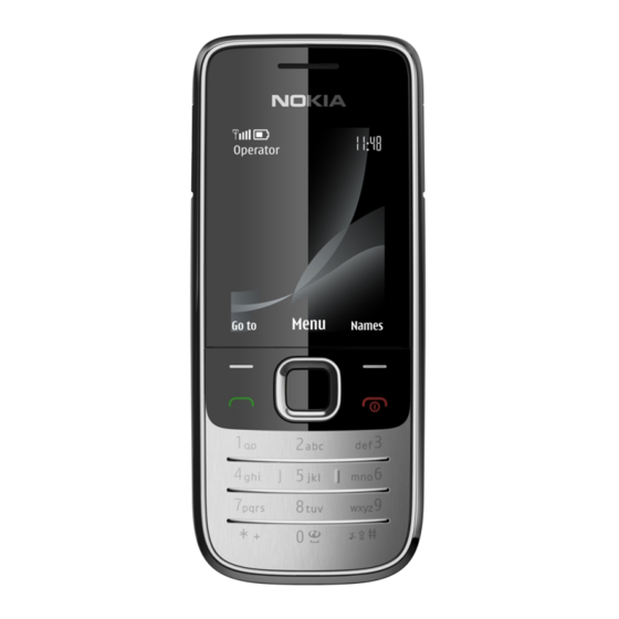
Table 1 Battery and chargers ..........................1–7 Table 2 Headsets ..............................1–7 Table 3 Data cables ..............................1–7 List of Figures Figure 1 RM-578/579 (Nokia 2730c) product picture ..................1–5 Issue 3 COMPANY CONFIDENTIAL Page 1 –3 Copyright © 2009 Nokia. All rights reserved. - Page 16 RM-578; RM-579 General information (This page left intentionally blank.) Page 1 –4 COMPANY CONFIDENTIAL Issue 3 Copyright © 2009 Nokia. All rights reserved.
-
Page 17: Product Selection
• 2730c classic • 2730 classic Marketing Name • 2730c (China mainland) Figure 1 RM-578/579 (Nokia 2730c) product picture Phone features Display and keypad features • 2” 240x320 pixel, 262k true colour display • 5-way , navi-key (2 soft-keys, call and end keys) Hardware features •... -
Page 18: User Interface And Software Features
• Nokia Charger: AC-3 (AC-8C and CA-100C for PRC) • 1GB micro SD memory card (area dependent) • Nokia wired stereo headset: WH-102 • User Guide Page 1 –6 COMPANY CONFIDENTIAL Issue 3 Copyright © 2009 Nokia. All rights reserved. -
Page 19: Technical Specifications
General information Table 1 Battery and chargers Type Name Note: This phone is charged through the smaller charger Nokia standard interface (2.mm plug). The standard 3.5mm standard charger can be used together with the CA-44 charger adapter. AC-3 Charger BL-5C... - Page 20 RM-578; RM-579 General information (This page left intentionally blank.) Page 1 –8 COMPANY CONFIDENTIAL Issue 3 Copyright © 2009 Nokia. All rights reserved.
- Page 21 Nokia Customer Care 2 — Service Devices and Service Concepts Issue 3 COMPANY CONFIDENTIAL Page 2 –1 Copyright © 2009 Nokia. All rights reserved.
- Page 22 RM-578; RM-579 Service Devices and Service Concepts (This page left intentionally blank.) Page 2 –2 COMPANY CONFIDENTIAL Issue 3 Copyright © 2009 Nokia. All rights reserved.
-
Page 23: Table Of Contents
..........................2–16 Figure 3 Basic flash concept with FPS-10......................2–17 Figure 4 CU-4 flash concept with FPS-10......................2–18 Figure 5 Module jig service concept ........................2–19 Issue 3 COMPANY CONFIDENTIAL Page 2 –3 Copyright © 2009 Nokia. All rights reserved. - Page 24 Figure 8 BB5 Basic Flash Concept with FPS-21, SS-62 ..................2–22 Figure 9 BB5 Basic RF & BB Tune Concept with FS-132..................2–23 Figure 10 BB5 Basic RF&BB Tune Concept with MJ-253 ................... 2–24 Page 2 –4 COMPANY CONFIDENTIAL Issue 3 Copyright © 2009 Nokia. All rights reserved.
-
Page 25: Service Devices
The table below gives a short overview of service devices that can be used for testing, error analysis, and repair of product RM-578; RM-579. For the correct use of the service devices, and the best effort of workbench setup, please refer to various concepts. -
Page 26: General Devices
The table below gives a short overview of service devices that can be used for testing, error analysis, and repair of product RM-578; RM-579. For the correct use of the service devices, and the best effort of workbench setup, please refer to various concepts. - Page 27 4 Connect an FBUS cable (if necessary). 5 Start Phoenix service software. Note: Phoenix enables CU-4 regulators via USB when it is started. Reconnecting the power supply requires a Phoenix restart. Issue 3 COMPANY CONFIDENTIAL Page 2 –7 Copyright © 2009 Nokia. All rights reserved.
- Page 28 FPS-10 sales package includes: • FPS-10 prommer • Power Supply with 5 country specific cords • USB cable Note: FPS-21 is substitute FPS-10 if FPS-10 has not been set Page 2 –8 COMPANY CONFIDENTIAL Issue 3 Copyright © 2009 Nokia. All rights reserved.
-
Page 29: Fps-21
PK-1 is meant for use with a PC that does not have a series interface. To use this USB dongle for security service functions please register the dongle in the same way as the PKD-1 series dongle. Issue 3 COMPANY CONFIDENTIAL Page 2 –9 Copyright © 2009 Nokia. All rights reserved. - Page 30 January 2009. For all new parts needing solder paste support after January 1, 2009, please contact your solder machine manufacturer for the universal solutions for solder paste application for rework purposes. Page 2 –10 COMPANY CONFIDENTIAL Issue 3 Copyright © 2009 Nokia. All rights reserved.
- Page 31 Service Devices and Service Concepts SRT-6 Opening tool SRT-6 is used to open phone covers. Note: The SRT-6 is included in the Nokia Standard Toolkit. SS-108 Peeling tool The peeling tool SS-108 is used to peel off the shielding. SS-203...
-
Page 32: Cables
The table below gives a short overview of service devices that can be used for testing, error analysis, and repair of product RM-578; RM-579. For the correct use of the service devices, and the best effort of workbench setup, please refer to various concepts. -
Page 33: Ca-112Ds
CA-35S is a power cable for connecting, for example, the FPS-21 flash prommer to the Point-Of-Sales (POS) flash adapter. CA-89DS Cable Provides VBAT and Flashbus connections to mobile device programming adapters. Issue 3 COMPANY CONFIDENTIAL Page 2 –13 Copyright © 2009 Nokia. All rights reserved. -
Page 34: Ca-99Ps
XCS-4 Modular cable XCS-4 is a shielded (one specially shielded conductor) modular cable for flashing and service purposes. Page 2 –14 COMPANY CONFIDENTIAL Issue 3 Copyright © 2009 Nokia. All rights reserved. - Page 35 The RF cable is used to connect, for example, a module repair jig to the RF measurement equipment. SMA to N-Connector approximately 610 mm. Attenuation for: • GSM850/900: 0.3+-0.1 dB • GSM1800/1900: 0.5+-0.1 dB • WLAN: 0.6+-0.1dB Issue 3 COMPANY CONFIDENTIAL Page 2 –15 Copyright © 2009 Nokia. All rights reserved.
-
Page 36: Service Concepts
Figure 2 POS flash concept Type Description Product specific tools BL-5C Battery Other tools FLS-5 POS flash dongle PC with Phoenix service software Cables CA-101 USB connectivity cable Page 2 –16 COMPANY CONFIDENTIAL Issue 3 Copyright © 2009 Nokia. All rights reserved. -
Page 37: Flash Concept With Fps-10
Other devices FPS-10 Flash prommer box PKD-1/PK-1 SW security device SS-46 Interface adapter PC with Phoenix service software Cables XCS-4 Modular cable CA-35S Power cable USB cable Issue 3 COMPANY CONFIDENTIAL Page 2 –17 Copyright © 2009 Nokia. All rights reserved. -
Page 38: Flash Concept With Fps-10
SW security device SS-62 Flash adapter base SX-4 Smart card PC with Phoenix service software Cables PCS-1 Power cable XCS-4 Modular cable Standard USB cable USB cable Page 2 –18 COMPANY CONFIDENTIAL Issue 3 Copyright © 2009 Nokia. All rights reserved. -
Page 39: Module Jig Service Concept
SW security device SX-4 Smart card PC with VPOS and Phoenix service software Measurement equipment Cables PCS-1 DC power cable XCS-4 Modular cable XRS-6 RF cable USB cable Issue 3 COMPANY CONFIDENTIAL Page 2 –19 Copyright © 2009 Nokia. All rights reserved. -
Page 40: Rf Testing Concept With Rf Coupler
SX-4 Smart card FPS-10 Flash prommer box PKD-1/PK-1 SW security device SS-62 Flash adapter base Measurement equipment PC with Phoenix service software Cables PCS-1 Power cable Page 2 –20 COMPANY CONFIDENTIAL Issue 3 Copyright © 2009 Nokia. All rights reserved. -
Page 41: Bb5 Basic Flash Concept With Fps-21, Ss-46
Modular cable XRS-6 RF cable GPIB control cable USB cable BB5 Basic Flash Concept with FPS-21, SS-46 Figure 7 BB5 Basic Flash Concept with FPS-21, SS-46 Issue 3 COMPANY CONFIDENTIAL Page 2 –21 Copyright © 2009 Nokia. All rights reserved. -
Page 42: Bb5 Basic Flash Concept With
RM-578; RM-579 Service Devices and Service Concepts BB5 Basic Flash Concept with FPS-21, SS-62 Figure 8 BB5 Basic Flash Concept with FPS-21, SS-62 Page 2 –22 COMPANY CONFIDENTIAL Issue 3 Copyright © 2009 Nokia. All rights reserved. -
Page 43: Bb5 Basic Rf & Bb Tune Concept With Fs-132
RM-578; RM-579 Service Devices and Service Concepts BB5 Basic RF & BB Tune Concept with FS-132 Figure 9 BB5 Basic RF & BB Tune Concept with FS-132 Issue 3 COMPANY CONFIDENTIAL Page 2 –23 Copyright © 2009 Nokia. All rights reserved. -
Page 44: Bb5 Basic Rf&Bb Tune Concept With
RM-578; RM-579 Service Devices and Service Concepts BB5 Basic RF&BB Tune Concept with MJ-253 Figure 10 BB5 Basic RF&BB Tune Concept with MJ-253 Page 2 –24 COMPANY CONFIDENTIAL Issue 3 Copyright © 2009 Nokia. All rights reserved. - Page 45 Nokia Customer Care 3 — BB Troubleshooting and Manual Tuning Guide Issue 3 COMPANY CONFIDENTIAL Page 3 –1 Copyright © 2009 Nokia. All rights reserved.
- Page 46 RM-578; RM-579 BB Troubleshooting and Manual Tuning Guide (This page left intentionally blank.) Page 3 –2 COMPANY CONFIDENTIAL Issue 3 Copyright © 2009 Nokia. All rights reserved.
- Page 47 Figure 14 Differential output waveform of the Ext_in_IHF_out out loop measurement when speaker is connected..............................3–28 Figure 15 Single-ended output waveform of the HP_in_Ext_out loop when microphone is connected. 3–29 Issue 3 COMPANY CONFIDENTIAL Page 3 –3 Copyright © 2009 Nokia. All rights reserved.
- Page 48 RM-578; RM-579 BB Troubleshooting and Manual Tuning Guide (This page left intentionally blank.) Page 3 –4 COMPANY CONFIDENTIAL Issue 3 Copyright © 2009 Nokia. All rights reserved.
-
Page 49: Baseband Self Tests In Phoenix
Always start the troubleshooting procedure by running the Phoenix self tests. If a test fails, please follow the diagram below. Dead or jammed device troubleshooting. If the phone is dead and you cannot perform the self tests, go to Issue 3 COMPANY CONFIDENTIAL Page 3 –5 Copyright © 2009 Nokia. All rights reserved. - Page 50 RM-578; RM-579 BB Troubleshooting and Manual Tuning Guide Troubleshooting flow Page 3 –6 COMPANY CONFIDENTIAL Issue 3 Copyright © 2009 Nokia. All rights reserved.
-
Page 51: Power And Charging Troubleshooting
RM-578; RM-579 BB Troubleshooting and Manual Tuning Guide Power and charging troubleshooting Dead or jammed device troubleshooting Troubleshooting flow Issue 3 COMPANY CONFIDENTIAL Page 3 –7 Copyright © 2009 Nokia. All rights reserved. - Page 52 RM-578; RM-579 BB Troubleshooting and Manual Tuning Guide Troubleshooting flow Page 3 –8 COMPANY CONFIDENTIAL Issue 3 Copyright © 2009 Nokia. All rights reserved.
-
Page 53: General Power Checking
RF active VREF AVILMA 1.35 RF reference VCORE BETTY 1.05 Combo memory 1.25 1.35 1.40 VOUT BETTY Accessory connected VSIM2 AVILMA Internal microphone Charging troubleshooting Troubleshooting flow Issue 3 COMPANY CONFIDENTIAL Page 3 –9 Copyright © 2009 Nokia. All rights reserved. - Page 54 RM-578; RM-579 BB Troubleshooting and Manual Tuning Guide Page 3 –10 COMPANY CONFIDENTIAL Issue 3 Copyright © 2009 Nokia. All rights reserved.
-
Page 55: Interface Troubleshooting
RM-578; RM-579 BB Troubleshooting and Manual Tuning Guide Interface troubleshooting Flash programming fault troubleshooting Part 1 Issue 3 COMPANY CONFIDENTIAL Page 3 –11 Copyright © 2009 Nokia. All rights reserved. - Page 56 RM-578; RM-579 BB Troubleshooting and Manual Tuning Guide Part 2 Figure 11 Flashing pic 1. Take single trig measurement for the rise of the BSI signal. Page 3 –12 COMPANY CONFIDENTIAL Issue 3 Copyright © 2009 Nokia. All rights reserved.
- Page 57 RM-578; RM-579 BB Troubleshooting and Manual Tuning Guide Figure 12 Flashing pic 2. Take single trig measurement for the rise of the BSI signal. Issue 3 COMPANY CONFIDENTIAL Page 3 –13 Copyright © 2009 Nokia. All rights reserved.
-
Page 58: Combo Memory Troubleshooting
RM-578; RM-579 BB Troubleshooting and Manual Tuning Guide Combo memory troubleshooting Troubleshooting flow Page 3 –14 COMPANY CONFIDENTIAL Issue 3 Copyright © 2009 Nokia. All rights reserved. -
Page 59: Usb Interface Troubleshooting
RM-578; RM-579 BB Troubleshooting and Manual Tuning Guide USB interface troubleshooting Troubleshooting flow Issue 3 COMPANY CONFIDENTIAL Page 3 –15 Copyright © 2009 Nokia. All rights reserved. -
Page 60: Sim Card Troubleshooting
RM-578; RM-579 BB Troubleshooting and Manual Tuning Guide SIM card troubleshooting Troubleshooting flow Page 3 –16 COMPANY CONFIDENTIAL Issue 3 Copyright © 2009 Nokia. All rights reserved. - Page 61 RM-578; RM-579 BB Troubleshooting and Manual Tuning Guide Issue 3 COMPANY CONFIDENTIAL Page 3 –17 Copyright © 2009 Nokia. All rights reserved.
-
Page 62: User Interface Troubleshooting
• Malfunction of several keys at the same time; this happens when one or more rows or columns in the key matrix are failing (shortcut or open connection). If the failure mode is not clear, start with the Keyboard test in Phoenix. Page 3 –18 COMPANY CONFIDENTIAL Issue 3 Copyright © 2009 Nokia. All rights reserved. - Page 63 RM-578; RM-579 BB Troubleshooting and Manual Tuning Guide Troubleshooting flow Issue 3 COMPANY CONFIDENTIAL Page 3 –19 Copyright © 2009 Nokia. All rights reserved.
-
Page 64: Display Module Troubleshooting
Total Combine Not allowed. d defect Two single dot defects that are within 5 mm of each other should counts be interpreted as combined dot defect. Page 3 –20 COMPANY CONFIDENTIAL Issue 3 Copyright © 2009 Nokia. All rights reserved. -
Page 65: Display Troubleshooting
RM-578; RM-579 BB Troubleshooting and Manual Tuning Guide Display troubleshooting Troubleshooting flow Issue 3 COMPANY CONFIDENTIAL Page 3 –21 Copyright © 2009 Nokia. All rights reserved. -
Page 66: Keyboard Backlight Troubleshooting
RM-578; RM-579 BB Troubleshooting and Manual Tuning Guide Keyboard backlight troubleshooting Troubleshooting flow Page 3 –22 COMPANY CONFIDENTIAL Issue 3 Copyright © 2009 Nokia. All rights reserved. -
Page 67: Sd Card Troubleshooting
RM-578; RM-579 BB Troubleshooting and Manual Tuning Guide SD card troubleshooting Troubleshooting flow Issue 3 COMPANY CONFIDENTIAL Page 3 –23 Copyright © 2009 Nokia. All rights reserved. -
Page 68: Camera Troubleshooting
RM-578; RM-579 BB Troubleshooting and Manual Tuning Guide Camera troubleshooting Camera troubleshooting Troubleshooting flow Page 3 –24 COMPANY CONFIDENTIAL Issue 3 Copyright © 2009 Nokia. All rights reserved. - Page 69 RM-578; RM-579 BB Troubleshooting and Manual Tuning Guide Issue 3 COMPANY CONFIDENTIAL Page 3 –25 Copyright © 2009 Nokia. All rights reserved.
-
Page 70: Audio Troubleshooting
Earpiece, internal microphone and speaker are in place during measurement. Applying a headset accessory during measurement causes a significant drop in measured quantities. The gain values presented in the table apply for a differential output vs. single-ended/differential input. Page 3 –26 COMPANY CONFIDENTIAL Issue 3 Copyright © 2009 Nokia. All rights reserved. - Page 71 XMICN and B2101 pads Internal Mic to B2150 HSEAR R P, 22.7 1360 External Earpiece (OUT/GND) HSEAR R N and GND HSEAR P, HSEAR N and GND Issue 3 COMPANY CONFIDENTIAL Page 3 –27 Copyright © 2009 Nokia. All rights reserved.
- Page 72 If a special low-pass filter designed for measuring digital amplifiers is unavailable, the measurement must be performed with a current probe and the input signal frequency must be 2kHz. Figure 14 Differential output waveform of the Ext_in_IHF_out out loop measurement when speaker is connected. Page 3 –28 COMPANY CONFIDENTIAL Issue 3 Copyright © 2009 Nokia. All rights reserved.
- Page 73 RM-578; RM-579 BB Troubleshooting and Manual Tuning Guide Figure 15 Single-ended output waveform of the HP_in_Ext_out loop when microphone is connected. Issue 3 COMPANY CONFIDENTIAL Page 3 –29 Copyright © 2009 Nokia. All rights reserved.
-
Page 74: Internal Earpiece Troubleshooting
RM-578; RM-579 BB Troubleshooting and Manual Tuning Guide Internal earpiece troubleshooting Troubleshooting flow Page 3 –30 COMPANY CONFIDENTIAL Issue 3 Copyright © 2009 Nokia. All rights reserved. -
Page 75: Internal Microphone Troubleshooting
RM-578; RM-579 BB Troubleshooting and Manual Tuning Guide Internal microphone troubleshooting Troubleshooting flow Issue 3 COMPANY CONFIDENTIAL Page 3 –31 Copyright © 2009 Nokia. All rights reserved. -
Page 76: Internal Handsfree (Ihf) Troubleshooting
RM-578; RM-579 BB Troubleshooting and Manual Tuning Guide Internal handsfree (IHF) troubleshooting Troubleshooting flow Page 3 –32 COMPANY CONFIDENTIAL Issue 3 Copyright © 2009 Nokia. All rights reserved. -
Page 77: External Earpiece Troubleshooting
RM-578; RM-579 BB Troubleshooting and Manual Tuning Guide External earpiece troubleshooting Troubleshooting flow Issue 3 COMPANY CONFIDENTIAL Page 3 –33 Copyright © 2009 Nokia. All rights reserved. -
Page 78: External Microphone Troubleshooting
RM-578; RM-579 BB Troubleshooting and Manual Tuning Guide External microphone troubleshooting Troubleshooting flow Page 3 –34 COMPANY CONFIDENTIAL Issue 3 Copyright © 2009 Nokia. All rights reserved. -
Page 79: Vibra Troubleshooting
RM-578; RM-579 BB Troubleshooting and Manual Tuning Guide Vibra troubleshooting Troubleshooting flow Issue 3 COMPANY CONFIDENTIAL Page 3 –35 Copyright © 2009 Nokia. All rights reserved. -
Page 80: Baseband Manual Tuning Guide
Note: USB flashing does not work for a dead BB5 phone. • Create a request file. • Send the file to Nokia by e-mail. Use the following addresses depending on your location: • APAC: sydney.service@nokia.com • CHINA: repair.ams@nokia.com • E&A: salo.repair@nokia.com •... - Page 81 For this procedure, you must supply +12 V to CU-4 from an external power supply. Phoenix , choose File→Scan Product . To connect the phone with ii Choose Tools→Certificate Restore . Issue 3 COMPANY CONFIDENTIAL Page 3 –37 Copyright © 2009 Nokia. All rights reserved.
- Page 82 Request file, click Start. To create the vi When the file for certificate restore has been created, send it to Nokia as an e-mail attachment. 3. Restore certificate. For this procedure, you must supply +12 V to CU-4 from an external power supply.
- Page 83 To write the file to phone, click Start. Next actions Phoenix tuning functions. After a successful rewrite, you must retune the phone completely by using Important: Perform all tunings: RF, BB, and UI. Issue 3 COMPANY CONFIDENTIAL Page 3 –39 Copyright © 2009 Nokia. All rights reserved.
-
Page 84: Energy Management Calibration
Write and/or repeat the procedure again. Energy Management Calibration window. 10. To end the procedure, close the Page 3 –40 COMPANY CONFIDENTIAL Issue 3 Copyright © 2009 Nokia. All rights reserved. - Page 85 Nokia Customer Care 4 — RF troubleshooting Issue 3 COMPANY CONFIDENTIAL Page 4 –1 Copyright © 2009 Nokia. All rights reserved.
- Page 86 RM-578; RM-579 RF troubleshooting (This page left intentionally blank.) Page 4 –2 COMPANY CONFIDENTIAL Issue 3 Copyright © 2009 Nokia. All rights reserved.
- Page 87 Figure 25 Example of Varactor Tuning values across the FM Band ..............4–24 Figure 26 Troubleshooting diagram: Bluetooth ....................4–27 Figure 27 WCDMA RX test points ........................4–31 Figure 28 WCDMA TX test points ........................4–32 Issue 3 COMPANY CONFIDENTIAL Page 4 –3 Copyright © 2009 Nokia. All rights reserved.
- Page 88 RM-578; RM-579 RF troubleshooting (This page left intentionally blank.) Page 4 –4 COMPANY CONFIDENTIAL Issue 3 Copyright © 2009 Nokia. All rights reserved.
-
Page 89: General Rf Troubleshooting
RF shielded environment, testing at frequencies of nearby base stations should be avoided. Level of repair The scope of this guideline is to enable repairs at key-component level. Please refer to the troubleshooting instructions for further information. Issue 3 COMPANY CONFIDENTIAL Page 4 –5 Copyright © 2009 Nokia. All rights reserved. -
Page 90: Rf Key Components
Figure 17 Auto tuning concept with CMU200 Phoenix preparations RM-578_dp_1.78_sw_sh3.26.exe . This defines phone Install the phone specific data package, for example specific settings. Page 4 –6 COMPANY CONFIDENTIAL Issue 3 Copyright © 2009 Nokia. All rights reserved. -
Page 91: General Voltage Checking
Signal name Test point Voltage (all bands) Vbat at N7520 (FEM) J2903 3.0-4.7 V Vbat at N7505 (Transceiver) C2070 3.0-4.7 V VCCXO supply C2213 2.4-2.6 V Issue 3 COMPANY CONFIDENTIAL Page 4 –7 Copyright © 2009 Nokia. All rights reserved. -
Page 92: Selftest Troubleshooting
Testing→GSM→RF Controls→ RX and then press Stop. Context Note: The RF connector should be terminated to 50 Ohms or connected to the antenna. Check this carefully before performing the self tests. Page 4 –8 COMPANY CONFIDENTIAL Issue 3 Copyright © 2009 Nokia. All rights reserved. - Page 93 RF troubleshootings. 3. If Fatal, press Details to see error codes Detailed . Error codes will now show up in the right most column marked Issue 3 COMPANY CONFIDENTIAL Page 4 –9 Copyright © 2009 Nokia. All rights reserved.
-
Page 94: Fatal Selftests Troubleshooting
If a self test is fatal, check the Details→Error code and follow the instructions below. Note: If ST_CDSP_RF_BB_IF_TEST is fatal, the other self tests will also be fatal. Always start troubleshooting ST_CDSP_RF_BB_IF_TEST. Page 4 –10 COMPANY CONFIDENTIAL Issue 3 Copyright © 2009 Nokia. All rights reserved. - Page 95 Figure 19 Testpoints used after fatal self tests ST_CDSP_RF_BB_IF_TEST is fatal This test is checking the communication between baseband and RF. It will show in what part the problem is located. Issue 3 COMPANY CONFIDENTIAL Page 4 –11 Copyright © 2009 Nokia. All rights reserved.
- Page 96 1 J2210 TXBB_CLK (Ch1) [4] 2 J2212 TXBB_DATA (Ch2) [5] 3 J2902 STROBE (Ch3) [6] The result should look like this: Figure 21 Settings: Time 1ns/d + 0.3Vpp/d Page 4 –12 COMPANY CONFIDENTIAL Issue 3 Copyright © 2009 Nokia. All rights reserved.
- Page 97 This test is checking the analogue RX communication between baseband and RF. Error code Test Action ST_FIMRCAL_FAIL (0x00, 0x40) Replace N7505 or combination (0x00, 0x50) and (0x00, 0x60) Issue 3 COMPANY CONFIDENTIAL Page 4 –13 Copyright © 2009 Nokia. All rights reserved.
-
Page 98: Receiver Troubleshooting
Introduction to receiver (RX) troubleshooting RX can be tested by making a phone call or in local mode. For the local mode testing, use Phoenix service software. Page 4 –14 COMPANY CONFIDENTIAL Issue 3 Copyright © 2009 Nokia. All rights reserved. -
Page 99: Gsm Rx Chain Activation For Manual Measurements/Gsm Rssi Measurement
Now select the measuring mode to the signal generator level. Next actions RSSI-reading AND TX troubleshooting is failing: replace N7520. TX is OK and RX is failing: replace N7505. Issue 3 COMPANY CONFIDENTIAL Page 4 –15 Copyright © 2009 Nokia. All rights reserved. -
Page 100: Transmitter Troubleshooting
GSM transmitter troubleshooting Steps 1. Set the phone to local mode. 2. Activate RF controls in Phoenix (Testing→GSM→Rf Controls ). Make settings as shown in the picture: Page 4 –16 COMPANY CONFIDENTIAL Issue 3 Copyright © 2009 Nokia. All rights reserved. - Page 101 RF troubleshooting 3. Check the basic TX parameters (i.e. power, phase error, modulation and switching spectrum), using a communication analyser (for example CMU200). Figure 23 Typical readings Issue 3 COMPANY CONFIDENTIAL Page 4 –17 Copyright © 2009 Nokia. All rights reserved.
-
Page 102: Bluetooth And Fm Radio Troubleshooting
The FM transmitter antenna is product specific and is typically integrated into the phone mechanics (for example a loop antenna integrated into phone covers). The FM transmitter audio input signal is routed from the phone BB section to the Bluetooth-FM ASIC. Page 4 –18 COMPANY CONFIDENTIAL Issue 3 Copyright © 2009 Nokia. All rights reserved. -
Page 103: Symptom, Problem And Repair Solution
Open circuit solder joints or Replacement of Bluetooth/FM Bluetooth device, but unable to component failure of BTH/FM ASIC/module hear audio through functional ASIC/module BB ASICs (PCM Bluetooth headset interface). Issue 3 COMPANY CONFIDENTIAL Page 4 –19 Copyright © 2009 Nokia. All rights reserved. -
Page 104: Test Coverage
FM radio) Test Coverage The tests listed in the table below should be performed to verify whether the Bluetooth and FM receiver and transmitter are functional. Page 4 –20 COMPANY CONFIDENTIAL Issue 3 Copyright © 2009 Nokia. All rights reserved. -
Page 105: Test Procedure
Steps: 1 Place the phone in the flash adapter or connect data cable to phone. 2 Start Phoenix service software. 3 Choose File → Scan Product. Issue 3 COMPANY CONFIDENTIAL Page 4 –21 Copyright © 2009 Nokia. All rights reserved. - Page 106 6 In the Bluetooth LOCALS window, write the 12-digit serial number on the Counterpart BT Device Address line. 7 Place the BT-box near (within 10 cm) of the phone and click Run BER Test. Page 4 –22 COMPANY CONFIDENTIAL Issue 3 Copyright © 2009 Nokia. All rights reserved.
- Page 107 BTHFM ASIC. The test limits for the antenna tuning varactor value are product specific. Issue 3 COMPANY CONFIDENTIAL Page 4 –23 Copyright © 2009 Nokia. All rights reserved.
- Page 108 Figure 25 Example of Varactor Tuning values across the FM Band FM transmitter Alignment The auto-tune test set up with Rhode & Schwarz CMU200 (minimum firmware version 4.10) is shown below: Page 4 –24 COMPANY CONFIDENTIAL Issue 3 Copyright © 2009 Nokia. All rights reserved.
- Page 109 4 Choose Tuning → FM Radio Auto-Tune. 5 Check that the Scan for Instruments checkbox is enabled and click the Tune button. If successful then the following dialogue should be displayed: Issue 3 COMPANY CONFIDENTIAL Page 4 –25 Copyright © 2009 Nokia. All rights reserved.
-
Page 110: Bluetooth Troubleshooting
RF troubleshooting Bluetooth troubleshooting Troubleshooting flow The specific troubleshooting fault repair chart only needs to be followed if there is a fault with a particular function. Page 4 –26 COMPANY CONFIDENTIAL Issue 3 Copyright © 2009 Nokia. All rights reserved. - Page 111 RM-578; RM-579 RF troubleshooting Figure 26 Troubleshooting diagram: Bluetooth Issue 3 COMPANY CONFIDENTIAL Page 4 –27 Copyright © 2009 Nokia. All rights reserved.
-
Page 112: Fm Receiver Troubleshooting
RM-578; RM-579 RF troubleshooting FM receiver troubleshooting Troubleshooting flow Page 4 –28 COMPANY CONFIDENTIAL Issue 3 Copyright © 2009 Nokia. All rights reserved. -
Page 113: Fm Transmitter Troubleshooting
RM-578; RM-579 RF troubleshooting FM transmitter troubleshooting Troubleshooting flow WCDMA troubleshooting WCDMA RX Troubleshooting Preparations Set Phoenix to RF local mode WCDMA RX. Issue 3 COMPANY CONFIDENTIAL Page 4 –29 Copyright © 2009 Nokia. All rights reserved. - Page 114 Check the following Check the levels in the steps below. Signal Name Test point RXIP (OUT) J2810 RXQP (OUT) J2812 RXIN (OUT) J2811 RXQN (OUT) J2813 Page 4 –30 COMPANY CONFIDENTIAL Issue 3 Copyright © 2009 Nokia. All rights reserved.
-
Page 115: Wcdma Tx Troubleshooting
Set Phoenix to RF local mode WCDMA TX. Check the following Check the levels in the steps below. Signal Name Test point Check TXIP J2815 TXIN J2816 TXQP J2818 TXQN J2817 Issue 3 COMPANY CONFIDENTIAL Page 4 –31 Copyright © 2009 Nokia. All rights reserved. - Page 116 RM-578; RM-579 RF troubleshooting Figure 28 WCDMA TX test points Page 4 –32 COMPANY CONFIDENTIAL Issue 3 Copyright © 2009 Nokia. All rights reserved.
- Page 117 Nokia Customer Care 5 — System Module Issue 3 COMPANY CONFIDENTIAL Page 5 –1 Copyright © 2009 Nokia. All rights reserved.
- Page 118 RM-578; RM-579 System Module (This page left intentionally blank.) Page 5 –2 COMPANY CONFIDENTIAL Issue 3 Copyright © 2009 Nokia. All rights reserved.
-
Page 119: List Of Figures
Figure 31 SIM interface ............................5–10 Figure 32 Audio block diagram.......................... 5–12 Figure 33 Bluetooth interface ..........................5–15 Figure 34 Bluetooth & FM Radio Block Diagram....................5–18 Issue 3 COMPANY CONFIDENTIAL Page 5 –3 Copyright © 2009 Nokia. All rights reserved. - Page 120 RM-578; RM-579 System Module (This page left intentionally blank.) Page 5 –4 COMPANY CONFIDENTIAL Issue 3 Copyright © 2009 Nokia. All rights reserved.
-
Page 121: Introduction
D3000 Bluetooth BL6450 N6001 Battery BL-5C 1020mAh Battery connector Lynx interface X2070 µUSB connector For data, support USB full speed AV flex: X2002 Key component placement Issue 3 COMPANY CONFIDENTIAL Page 5 –5 Copyright © 2009 Nokia. All rights reserved. - Page 122 RM-578; RM-579 System Module System module block diagram Page 5 –6 COMPANY CONFIDENTIAL Issue 3 Copyright © 2009 Nokia. All rights reserved.
-
Page 123: Energy Management
The phone is powered by a 3-pole BL-5C 1020 mAh battery. The three poles are named VBAT, BSI and GND where the BSI line is used to recognize the battery capacity. This is done by means of an internal battery pull down resistor. Issue 3 COMPANY CONFIDENTIAL Page 5 –7 Copyright © 2009 Nokia. All rights reserved. -
Page 124: Normal And Extreme Voltages
In the table below normal and extreme voltages are shown when a BL-5C battery is used. Table 7 Nominal voltages Voltage Voltage [V] Condition General Conditions Nominal voltage Lower extreme voltage 3.145 Page 5 –8 COMPANY CONFIDENTIAL Issue 3 Copyright © 2009 Nokia. All rights reserved. -
Page 125: Power Key And System Power-Up
The micro USB (Universal Serial Bus) provides a wired connectivity between a PC and peripheral devices. It is a differential serial bus. USB 2.0 is supported with full speed (12 Mbps). Issue 3 COMPANY CONFIDENTIAL Page 5 –9 Copyright © 2009 Nokia. All rights reserved. -
Page 126: Sim Interface
The SIM interface supports both 1.8 V and 3.0 V SIM cards. The SIM interface voltage is first 1.8 V when the SIM card is inserted, and if the card does not response to the ATR a 3 V interface voltage is used. Page 5 –10 COMPANY CONFIDENTIAL Issue 3 Copyright © 2009 Nokia. All rights reserved. -
Page 127: Μsd Card Interface
ROW4 Backlight and illumination There is backlight illuminating for the display consisting of 2 LEDs. The keypad is side lit by 2 LEDs with film lightguide. Issue 3 COMPANY CONFIDENTIAL Page 5 –11 Copyright © 2009 Nokia. All rights reserved. -
Page 128: Audio Concept
AVILMAS N2200. One integrated handsfree speaker is driven directly by AVILMAS. The analog microphone is directly connected to AVILMAS for processing via a RF-filter. Figure 32 Audio block diagram Page 5 –12 COMPANY CONFIDENTIAL Issue 3 Copyright © 2009 Nokia. All rights reserved. -
Page 129: Av Connector
Table 9 AV connector pins Signal name Direction Description 1, 2 HS_ GND Ground HS_MIC Input Microphone HS_EAR_R Output Audio out HS_EAR_L Output Audio out PLUG_DET Input Plug detection Issue 3 COMPANY CONFIDENTIAL Page 5 –13 Copyright © 2009 Nokia. All rights reserved. -
Page 130: Rf Description
The frequency of this signal can be tuned to match the bandwidth of the system in use (eg. GSM900). The transmitter functions are implemented in the RF ASIC. Page 5 –14 COMPANY CONFIDENTIAL Issue 3 Copyright © 2009 Nokia. All rights reserved. -
Page 131: Bluetooth
GSM1900: 1930 - 1990 MHz TX frequency band GSM850: 824- 849 MHz GSM900: 880- 915 MHz GSM1800: 1710 - 1785 MHz GSM1900: 1850 - 1910 MHz Issue 3 COMPANY CONFIDENTIAL Page 5 –15 Copyright © 2009 Nokia. All rights reserved. -
Page 132: Environmental Conditions
Condensed or dripping water may cause intermittent malfunctions. Protection against dripping water has to be implemented in (enclosure) mechanics. Continuous dampness will cause permanent damage to the module. Page 5 –16 COMPANY CONFIDENTIAL Issue 3 Copyright © 2009 Nokia. All rights reserved. -
Page 133: Bthfmtxrds3.0B Technical Description
FM transmission to reduce the effect of interference from other FM transmitters. Block Diagram The following block diagram shows how Bluetooth-FM is connected to the host engine. Issue 3 COMPANY CONFIDENTIAL Page 5 –17 Copyright © 2009 Nokia. All rights reserved. -
Page 134: Interface Signals
FM Receiver Antenna Port TX_ANT FM Transmitter Antenna Port Clocking SYS_CLK Cellular engine RF clock (19.2, 26.0 or 38.4MHz) SLEEP_CLK Cellular engine sleep clock (32.768kHz) Bluetooth & FM Control Page 5 –18 COMPANY CONFIDENTIAL Issue 3 Copyright © 2009 Nokia. All rights reserved. - Page 135 STATUS Control signal to WLAN to indicate Bluetooth status Power Cellular engine I/O supply Alternative connection to 1.8V supply could be used VBAT Phone battery power Issue 3 COMPANY CONFIDENTIAL Page 5 –19 Copyright © 2009 Nokia. All rights reserved.
- Page 136 RM-578; RM-579 System Module (This page left intentionally blank.) Page 5 –20 COMPANY CONFIDENTIAL Issue 3 Copyright © 2009 Nokia. All rights reserved.
- Page 137 Nokia Customer Care Glossary Issue 3 COMPANY CONFIDENTIAL Page Glossary–1 Copyright © 2009 Nokia. All rights reserved.
- Page 138 RM-578; RM-579 Glossary (This page left intentionally blank.) Page Glossary–2 COMPANY CONFIDENTIAL Issue 3 Copyright © 2009 Nokia. All rights reserved.
- Page 139 Clock Timing Sleep and interrupt block of Tiku Continuous wave D/A-converter Digital-to-analogue converter Digital-to-analogue converter Digital Battery Interface DBus DSP controlled serial bus connected between UPP_WD2 and Helgo Issue 3 COMPANY CONFIDENTIAL Page Glossary–3 Copyright © 2009 Nokia. All rights reserved.
- Page 140 High speed circuit switched data (data transmission connection faster than GSM) Hardware Input/Output IBAT Battery current Integrated circuit ICHAR Charger current Interface Integrated hands free IMEI International Mobile Equipment Identity Page Glossary–4 COMPANY CONFIDENTIAL Issue 3 Copyright © 2009 Nokia. All rights reserved.
- Page 141 Software tool of DCT4.x and BB5 Personal Information Management Phase locked loop (Phone) Permanent memory General Purpose IO (PIO), USARTS and Pulse Width Modulators PURX Power-up reset Printed Wiring Board Issue 3 COMPANY CONFIDENTIAL Page Glossary–5 Copyright © 2009 Nokia. All rights reserved.
- Page 142 UEME Universal Energy Management chip (Enhanced version) UEMEK See UEME User Interface UPnP Universal Plug and Play Universal Phone Processor UPP_WD2 Communicator version of DCT4 system ASIC Page Glossary–6 COMPANY CONFIDENTIAL Issue 3 Copyright © 2009 Nokia. All rights reserved.
- Page 143 Wideband code division multiple access Watchdog WLAN Wireless local area network XHTML Extensible hypertext markup language Zocus Current sensor (used to monitor the current flow to and from the battery) Issue 3 COMPANY CONFIDENTIAL Page Glossary–7 Copyright © 2009 Nokia. All rights reserved.
- Page 144 RM-578; RM-579 Glossary (This page left intentionally blank.) Page Glossary–8 COMPANY CONFIDENTIAL Issue 3 Copyright © 2009 Nokia. All rights reserved.
Need help?
Do you have a question about the RM-579 and is the answer not in the manual?
Questions and answers