
Related Manuals for peerless-AV DST660


Summary of Contents for peerless-AV DST660
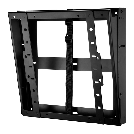
- Page 1 Installation and Assembly: Model: DST660 PORTRAIT LANDSCAPE Maximum Load Capacity: 125 lb (46 kg) 2300 White Oak Circle • Aurora, IL 60502 • (800) 865-2112 • Fax: (800) 359-6500 • www.peerlessmounts.com ISSUED: 12-16-11 SHEET #:125-9272-1...
-
Page 2: Table Of Contents
IMPORTANT! Read instruction sheet before you start installation and assembly. WARNING • Do not begin to install your Peerless product until you have read and understood the instructions and warnings contained in this Installation Sheet. If you have any questions regarding any of the instructions or warnings, for US customers please call Peerless customer care at 1-800-865-2112, for all international customers, please contact your local distributor. -
Page 3: Parts List
Parts List Description Qty. Part # A wall plate 145-1482 B adapter plate 145-1461 C #14 x 2.5" wood screw 5S1-015-C03 D concrete anchor 590-0320 E M8 x 12 mm phillips screw 520-9571 F M4 x 12 mm phillips screw 504-9013 G M5 x 12 mm phillips screw 520-1027... -
Page 4: Installation To Double Wood Stud Wall
Installation to Double Wood Stud Wall WARNING • Installer must verify that the supporting surface will safely support the combined load of the equipment and all attached hardware and components. • Tighten wood screws so that wall plate is firmly attached, but do not overtighten. Overtightening can damage the screws, greatly reducing their holding power. -
Page 5: Installation To Solid Concrete Or Cinder Block
WARNING • When installing Peerless wall mounts on cinder block, verify that you have a minimum of 1-3/8" of actual concrete thickness in the hole to be used for the concrete anchors. Do not drill into mortar joints! Be sure to mount in a solid part of the block, generally 1"... -
Page 6: Installation To Metal Stud Wall
Installation to Metal Studs WARNING • Drywall must be 1/2" or thicker, and metal stud must be 24 gauge or thicker. • Make sure that the wall will safely support the combined load of the equipment and all attached hardware and components. - Page 7 Placement of Adhesive Strips Place adhesive strips (K) on the wall plate (A) in location that will allow the most contact with CPU as shown in figure 2.1. Note: Placement of adhesive strips will vary depending on size of CPU as shown in figure 2.2 FRONT VIEW fig. 2.1 fig. 2.2...
-
Page 8: Attaching Adapter Plate To Screen
Attaching Adapter Plate to Display Determine hole pattern of display and fasteners used. Hand thread screws (E, F, G or H) through washers (J or O) and adapter brackets (R) into screen as shown in figure 4.1. WARNING • If screws don't get three complete turns in the screen inserts or if screws bottom out and bracket is still fig. 4.1 not tightly secured, damage may occur to screen or... -
Page 9: Attaching Adapter Plate To Wall Plate
Attaching Adapter Plate to Wall Plate Thread two M5 x 15 mm socket pin screws (Q) into bottom holes of wall plate (A) leaving 1/8" space between head of screw and wall plate as shown in figure 6.1. Guide hook slots of adapter plate (B) onto screws (Q), while supporting weight of screen, align top holes of wall plate and adapter bracket to the desired tilt angle and secure with two M5 x 15 mm socket pin screws (Q) as shown in figure 6.2.
Need help?
Do you have a question about the DST660 and is the answer not in the manual?
Questions and answers