Yaesu FTM-7250DR Technical Supplement
Vhf/uhf digital/analog transceiver
Hide thumbs
Also See for FTM-7250DR:
- Advance manual (42 pages) ,
- Operating manual (48 pages) ,
- Advance manual (42 pages)
Advertisement
Quick Links
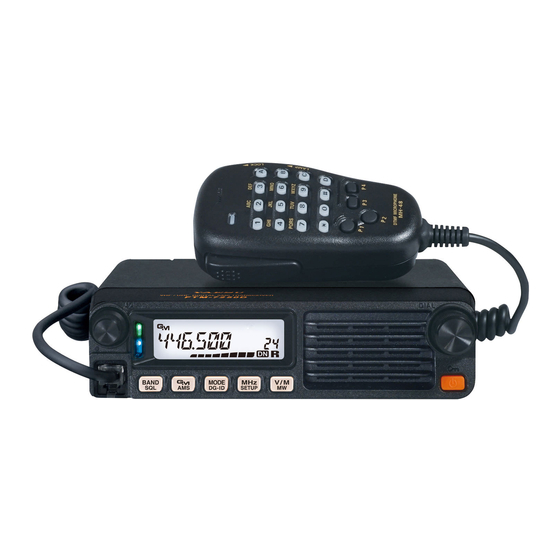
VHF/UHF DIGITAL/ANALOG TRANSCEIVER
FTM-7250DR/DE
Introduction
This manual provides the technical information necessary for ser-
vicing the FTM-7250DR/DE Transceiver.
Servicing this equipment requires expertise in handing surface-
mount chip components. Attempts by non-qualified persons
to service this equipment may result in permanent damage not
covered by the warranty, and may be illegal in some countries.
While we believe the information in this manual to be correct,
YAESU assumes no liability for damage that may occur as a
result of typographical or other errors that may be present. Your
cooperation in pointing out any inconsistencies in the technical
information would be appreciated.
This transceiver was assembled using Pb (lead) free solder, based on the RoHS specification.
Only lead-free solder (Alloy Composition: Sn-3.0Ag-0.5Cu) should be used for repairs performed on this apparatus. The solder stated
above utilizes the alloy composition required for compliance with the lead-free specification, and any solder with the above alloy com-
position may be used.
Technical Supplement
Specifications
Exploded View
Block Diagram
Alignment
Board Unit (Schematics, Layouts & Parts)
MAIN Unit
PANEL Unit
DSP Unit
Important Note
EH075M90B
©2019 YAESU MUSEN CO., LTD.
Contents
Advertisement

Related Manuals for Yaesu FTM-7250DR


Summary of Contents for Yaesu FTM-7250DR
- Page 1 Board Unit (Schematics, Layouts & Parts) While we believe the information in this manual to be correct, MAIN Unit YAESU assumes no liability for damage that may occur as a PANEL Unit result of typographical or other errors that may be present. Your...
- Page 2 3 W into 4 Ohms with 10% THD Specifications are subject to change without notice, and are guaranteed within the 144 and 430 MHz ama- teur bands only. Frequency ranges will vary according to transceiver version; check with your dealer. FTM-7250DR/DE Technical Supplement SPECIFICATIONS-1...
- Page 3 CQ0897001 PANEL Unit PANEL ASSY ⑦ ⑦ RA6070700 SPACER(SP) RA6069000 ⑦ COVER(CHASSIS) ⑦ RA606950A M4090262 VOLUME KNOB(ASSY) SPEAKER ⑦ RA6088100 RA6185100 RA6185300 REFLECTOR SHEET(LED) LIGHT GUIDE(LED) RUBBER KNOB RA6185700 FRONT PANEL ASSY RA606930A ENCODER KNOB(ASSY) EXPLODED VIEW-1 FTM-7250DR/DE Technical Supplement...
- Page 4 Block Diagram BLOCK DIAGRAM-1 FTM-7250DR/DE Technical Supplement...
- Page 5 Problems caused by unauthorized attempts at realignment are not covered by the warranty pol- icy. Also, YAESU must reserve the right to change circuits and alignment procedures in the interest of improved performance, without notifying owners.
- Page 6 13.8V DC for all steps. 50-Ohm Dummy Load Signal Generator RF Sampling Coupler Inline MIC INPUT MIC SW1 Wattmeter MIC SW2 PTT/CLONE DC INPUT Deviation Meter FTM-7250DR/DE SINAD Meter EXT SP Frequency Signal Generator Counter Test Equipment Setup MIC Jack FTM-7250DR/DE Technical Supplement ALIGNMENT-2...
- Page 7 9. Rotate the DIAL knob to select the Alignment Menu "tn". 10. Press the [ V/M ( MW )] key. 11. Adjust the DIAL knob so that the maximum- SINAD. 12. Press the [ V/M ( MW )] key. FTM-7250DR/DE Technical Supplement ALIGNMENT-3...
- Page 8 11. Press the [ BAND ( SQL )] key three times. 11. Press the [ BAND ( SQL )] key three times. 12. Press the [ V/M ( MW )] key. 12. Press the [ V/M ( MW )] key. FTM-7250DR/DE Technical Supplement ALIGNMENT-4...
- Page 9 11. Press the [ BAND ( SQL )] key three times. 11. Press the [ BAND ( SQL )] key three times. 12. Press the [ V/M ( MW )] key. 12. Press the [ V/M ( MW )] key. FTM-7250DR/DE Technical Supplement ALIGNMENT-5...
- Page 10 10. R e l e a s e t h e P T T s w i t c h , t h e n p r e s s t h e [ V/M ( MW )] key. [ V/M ( MW )] key. FTM-7250DR/DE Technical Supplement ALIGNMENT-6...
- Page 11 11. R e l e a s e t h e P T T s w i t c h , t h e n p r e s s t h e [ V/M ( MW )] key. FTM-7250DR/DE Technical Supplement ALIGNMENT-7...
- Page 12 Closing the Alignment mode 1. Press the [ GM ( AMS )] key to save the new set- ting and exit to normal operation. 2. The next time the transceiver is turned on, nor- mal operation will resume. FTM-7250DR/DE Technical Supplement ALIGNMENT-8...
- Page 13 MAIN Unit (Lot. 1) Circuit Diagram MAIN-1 FTM-7250DR/DE Technical Supplement...
- Page 14 MAIN Unit (Lot. 1) Parts Layout (Side A) MAIN-2 FTM-7250DR/DE Technical Supplement...
- Page 15 MAIN Unit (Lot. 1) Parts Layout (Side B) MAIN-3 FTM-7250DR/DE Technical Supplement...
- Page 16 MAIN Unit (Lot. 2) Circuit Diagram MAIN-4 FTM-7250DR/DE Technical Supplement...
- Page 17 MAIN Unit (Lot. 2) Parts Layout (Side A) MAIN-5 FTM-7250DR/DE Technical Supplement...
- Page 18 MAIN Unit (Lot. 2) Parts Layout (Side B) MAIN-6 FTM-7250DR/DE Technical Supplement...
- Page 19 MAIN Unit (Lot. 3 - 4) Circuit Diagram MAIN-7 FTM-7250DR/DE Technical Supplement...
- Page 20 MAIN Unit (Lot. 3 - 4) Parts Layout (Side A) MAIN-8 FTM-7250DR/DE Technical Supplement...
- Page 21 MAIN Unit (Lot. 3 - 4) Parts Layout (Side B) MAIN-9 FTM-7250DR/DE Technical Supplement...
- Page 22 MAIN Unit (Lot. 5 -) Circuit Diagram MAIN-10 FTM-7250DR/DE Technical Supplement...
- Page 23 MAIN Unit (Lot. 5 -) Parts Layout (Side A) MAIN-11 FTM-7250DR/DE Technical Supplement...
- Page 24 MAIN Unit (Lot. 5 -) Parts Layout (Side B) MAIN-12 FTM-7250DR/DE Technical Supplement...
- Page 25 GRM1552C1H220GA01D K22179707 C 1103 CHIP CAP. 0.01uF GRM155B11E103KA01D K22148834 C 1104 CHIP CAP. 0.001uF GRM155B11H102KA01D K22178809 C 1105 CHIP CAP. 12pF GRM1552C1H120GA01D K22179723 C 1106 CHIP CAP. 10pF GRM1552C1H100BA01D K22178297 C 1107 CHIP CAP. GRM21BB31E105KA98L K22140826 FTM-7250DR/DE Technical Supplement MAIN-13...
- Page 26 C 1250 CHIP CAP. 120pF 250V GQM2195C2E121JB12D K22240288 C 1251 CHIP CAP. 120pF 250V GQM2195C2E121JB12D K22240288 C 1253 CHIP CAP. 0.001uF GRM155B11H102KA01D K22178809 C 1254 CHIP CAP. 0.001uF GRM155B11H102KA01D K22178809 C 1258 CHIP CAP. 0.001uF GRM155B11H102KA01D K22178809 FTM-7250DR/DE Technical Supplement MAIN-14...
- Page 27 K22178838 C 1368 CHIP CAP. 0.0047uF GRM155B11H472KA01D K22178838 C 1401 CHIP CAP. 0.047uF GRM188B11E473KA01D K22144811 C 1402 CHIP CAP. 0.1uF GRM155B31E104KA87D K22148838 C 1403 CHIP CAP. 0.047uF GRM188B11E473KA01D K22144811 C 1404 CHIP CAP. 0.0022uF GRM155B11H222JA01D K22178837 FTM-7250DR/DE Technical Supplement MAIN-15...
- Page 28 GRM155B11H102KA01D K22178809 C 1521 CHIP CAP. 0.001uF GRM155B11H102KA01D K22178809 C 1522 CHIP CAP. GRM1554C1H2R0BA01D K22178289 C 1523 CHIP CAP. 47pF GRM1552C1H470GA01D K22179709 C 1523 CHIP CAP. 39pF GRM1552C1H390GA01D K22179703 C 1524 CHIP CAP. 12pF GRM1552C1H120GA01D K22179723 FTM-7250DR/DE Technical Supplement MAIN-16...
- Page 29 GRM155B11H102KA01D K22178809 C 1631 CHIP CAP. 0.001uF GRM155B11H102KA01D K22178809 C 1632 CHIP CAP. 22uF 6.3V GRM188R60J226MEA0D K22084807 C 1633 CHIP CAP. 47uF GRM31CR61A476ME15L K22101806 C 1634 CHIP CAP. GRM1552C1H8R0DA01D K22178210 C 1635 CHIP CAP. GRM1552C1H5R0CA01D K22178207 FTM-7250DR/DE Technical Supplement MAIN-17...
- Page 30 C 1839 CHIP CAP. 100pF GRM1882C1H101JA01D K22174235 C 1840 CHIP CAP. 0.001uF GRM155B11H102KA01D K22178809 C 1841 CHIP CAP. 0.001uF GRM1882C1H102JA01D K22174275 C 1842 CHIP CAP. 0.1uF GRM155B31E104KA87D K22148838 C 1842 CHIP CAP. 0.33uF 6.3V GRM155B10J334KE01D K22088801 FTM-7250DR/DE Technical Supplement MAIN-18...
- Page 31 1SS400 TE61 G2070634 D 1405 DIODE 1SS400 TE61 G2070634 D 1406 DIODE 1SS400 TE61 G2070634 D 1451 DIODE 1SS400 TE61 G2070634 D 1501 DIODE 1SV305(TPH3) G2070942 D 1502 DIODE 1SV305(TPH3) G2070942 D 1503 DIODE 1SV305(TPH3) G2070942 FTM-7250DR/DE Technical Supplement MAIN-19...
- Page 32 L1692070 L 1010 CHIP COIL 0.024uH LQW18AN24NG00D L1691787 L 1011 CHIP COIL 0.022uH LQW18AN22NG00D L1690884 L 1012 CHIP COIL 0.39uH LQW18ANR39G00D L1691786 L 1013 M.RFC 0.15uH LK1608 R15K-T L1690409 L 1014 CHIP COIL 0.39uH LQW18ANR39G00D L1691786 FTM-7250DR/DE Technical Supplement MAIN-20...
- Page 33 L 1602 M.RFC 0.047uH LQG18HH47NJ00D L1692094 L 1603 M.RFC 0.047uH LQG18HH47NJ00D L1692094 L 1604 M.RFC 0.082uH LQG18HH82NJ00D L1692100 L 1605 M.RFC 0.022uH LQG18HH22NJ00D L1692086 L 1607 M.RFC LK1608 1R0K-T L1690687 L 1631 M.RFC LK1608 1R0K-T L1690687 FTM-7250DR/DE Technical Supplement MAIN-21...
- Page 34 Q 1702 TRANSISTOR DTC143ZE TL G3070102 Q 1770 TRANSISTOR DTC143ZE TL G3070102 Q 1771 TRANSISTOR 2SC4617 TL R G3346178R Q 1801 SN74LV4053APWR G1093870 Q 1802 TRANSISTOR 2SC4081 T106 R G3340818R Q 1803 TRANSISTOR 2SC4081 T106 R G3340818R FTM-7250DR/DE Technical Supplement MAIN-22...
- Page 35 1/16W RMC1/16S 102JTH J24189025 R 1062 CHIP RES. 1/16W RMC1/16S 223JTH J24189041 R 1063 CHIP RES. 1/16W RMC1/16S 102JTH J24189025 R 1064 CHIP RES. 1/16W RMC1/16S 473JTH J24189045 R 1065 CHIP RES. 1/16W RMC1/16S 102JTH J24189025 FTM-7250DR/DE Technical Supplement MAIN-23...
- Page 36 CHIP RES. 1/16W RMC1/16 102FTP J24183102 R 1183 CHIP RES. 1/16W RMC1/16SK333FTH J24189494 R 1184 CHIP RES. 1/16W RMC1/16S 120JTH J24189002 R 1185 CHIP RES. 1/16W RMC1/16S 120JTH J24189002 R 1186 CHIP RES. 1/16W RMC1/16S 120JTH J24189002 FTM-7250DR/DE Technical Supplement MAIN-24...
- Page 37 1/16W RMC1/16S 271JTH J24189018 R 1325 CHIP RES. 1/16W RMC1/16S 221JTH J24189017 R 1326 CHIP RES. 1/16W RMC1/16S 271JTH J24189018 R 1327 CHIP RES. 1/16W RMC1/16S 221JTH J24189017 R 1328 CHIP RES. 1/16W RMC1/16S 271JTH J24189018 FTM-7250DR/DE Technical Supplement MAIN-25...
- Page 38 J24189053 R 1505 CHIP RES. 220k 1/16W RMC1/16S 224JTH J24189053 R 1506 CHIP RES. 1/16W RMC1/16S 101JTH J24189013 R 1507 CHIP RES. 100k 1/16W RMC1/16S 104JTH J24189049 R 1508 CHIP RES. 100k 1/16W RMC1/16S 104JTH J24189049 FTM-7250DR/DE Technical Supplement MAIN-26...
- Page 39 J24189025 R 1652 CHIP RES. 1/16W RMC1/16S 102JTH J24189025 R 1653 CHIP RES. 1/16W RMC1/16S JPTH J24189070 R 1655 CHIP RES. 1/16W RMC1/16S 103JTH J24189037 R 1656 CHIP RES. 1/16W RMC1/16S JPTH J24189070 VERSION A2 1- FTM-7250DR/DE Technical Supplement MAIN-27...
- Page 40 J24189047 R 1774 CHIP RES. 1/16W RMC1/16S 103JTH J24189037 R 1775 CHIP RES. 220k 1/16W RMC1/16S 224JTH J24189053 R 1776 CHIP RES. 270k 1/16W 0.5% MCR01MZPD2703 J24189329 R 1777 CHIP RES. 220k 1/16W RMC1/16S 224JTH J24189053 FTM-7250DR/DE Technical Supplement MAIN-28...
- Page 41 J24189045 R 1877 CHIP RES. 6.8k 1/16W RMC1/16S 682JTH J24189035 R 1878 CHIP RES. 1/16W RMC1/16 000JATP J24185000 R 1879 CHIP RES. 1/10W RMC1/10T 101J J24205101 RB1631 BLOCK RES. MNR04M0ABJ102 J42900039 RB1632 BLOCK RES. MNR04M0ABJ102 J42900039 FTM-7250DR/DE Technical Supplement MAIN-29...
- Page 42 CHOKE COIL DLP11SN900HL2L L1691732 TH1150 THERMISTOR NTCG164BH103JT1 G9090190 TH1151 THERMISTOR NTCG164BH103JT1 G9090190 TP1833 CHECK TERMINAL RCTCTE Q5000103 X 1040 VCTCXO 15.6MHz TTS14VSB-A3 15.60MHZ H9501310 X 1631 XTAL NX3225SA 16MHz 16.000MHZ H0103415 XF1451 XTAL FILTER D47215GQ3 47.250MHZ H1102483 FTM-7250DR/DE Technical Supplement MAIN-30...
- Page 43 PANEL Unit Circuit Diagram PANEL-1 FTM-7250DR/DE Technical Supplement...
- Page 44 PANEL Unit Parts Layout Side A Side B PANEL-2 FTM-7250DR/DE Technical Supplement...
- Page 45 L9190081 FB2004 FERRITE BEADS BK1608HS121-T L9190081 FB2005 FERRITE BEADS BK1608HS121-T L9190081 FB2006 FERRITE BEADS BK1608HS121-T L9190081 FB2007 FERRITE BEADS BLM15AG121SN1D L1690843 FB2008 FERRITE BEADS BLM15AG121SN1D L1690843 FB2009 FERRITE BEADS BLM15AG121SN1D L1690843 J 2001 CONNECTOR MJD0606KX06L P1091242 FTM-7250DR/DE Technical Supplement PANEL-3...
- Page 46 1/16W RMC1/16S 560JTH J24189010 R 2059 CHIP RES. 1/16W RMC1/16S 331JTH J24189019 R 2060 CHIP RES. 1/16W RMC1/16S 560JTH J24189010 R 2061 CHIP RES. 1/16W RMC1/16S 560JTH J24189010 R 2062 CHIP RES. 1/16W RMC1/16S JPTH J24189070 FTM-7250DR/DE Technical Supplement PANEL-4...
- Page 47 SKQMASE010 N5090092A S 2003 TACT SWITCH SKQMASE010 N5090092A S 2004 TACT SWITCH SKQMASE010 N5090092A S 2005 TACT SWITCH SKQMASE010 N5090092A S 2006 TACT SWITCH SKQMASE010 N5090092A S 2007 TACT SWITCH SKQMASE010 N5090092A VR2001 POT. RK09D1130C6Y J60800330 FTM-7250DR/DE Technical Supplement PANEL-5...
- Page 48 DSP Unit Circuit Diagram FTM-7250DR/DE Technical Supplement DSP-1...
- Page 49 DSP Unit Parts Layout Side A Side B FTM-7250DR/DE Technical Supplement DSP-2...
- Page 50 4.7k 1/16W RMC1/16S 472JTH J24189033 R 9027 CHIP RES. 1/16W RMC1/16S 473JTH J24189045 R 9032 CHIP RES. 1/16W RMC1/16S 473JTH J24189045 R 9033 CHIP RES. 1/16W RMC1/16SK393FTH J24189524 FTM-7250DR/DE Technical Supplement ø Please Contact YAESU when replacing this part. DSP-3...
- Page 51 R 9100 CHIP RES. 1/16W RMC1/16S 2R2JTH J24189602 R 9101 CHIP RES. 100k 1/16W RMC1/16SK104FTH J24189529 R 9102 CHIP RES. 1/16W RMC1/16S JPTH J24189070 SC9001 SHIELD CASE (DSP) RA1357400 X 9001 TCXO 18.432MHz DSB321SDN 18.432MHZ H9501840 FTM-7250DR/DE Technical Supplement DSP-4...
- Page 52 Copyright 2019 YAESU MUSEN CO., LTD. All rights reserved. No portion of this manual may be reproduced without the permission of YAESU MUSEN CO., LTD. YAESU MUSEN CO., LTD. Tennozu Parkside Building 2-5-8 Higashi-Shinagawa, Shinagawa-ku, Tokyo 140-0002 Japan YAESU USA 6125 Phyllis Drive, Cypress, CA 90630, U.S.A.
Need help?
Do you have a question about the FTM-7250DR and is the answer not in the manual?
Questions and answers