
Related Manuals for CHESTER T Mill


Summary of Contents for CHESTER T Mill
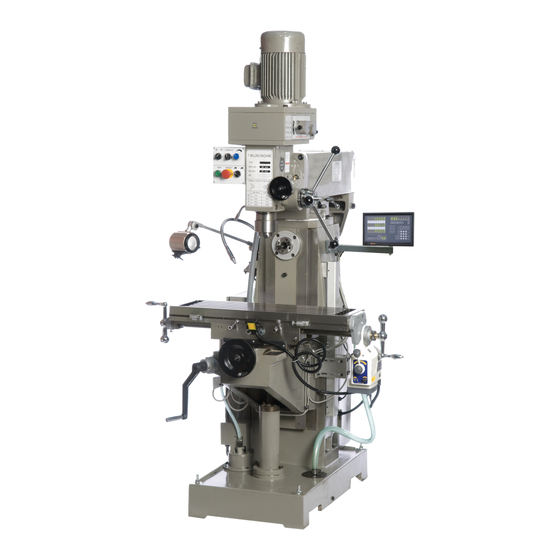
- Page 1 T Mill Milling Machine Operation Manual Chester UK Ltd Clwyd Close Hawarden Industrial Park Hawarden Chester CH5 3PZ Tel: 01244 531631 sales@chestermachinetools.com www.chestermachinetools.com...
-
Page 2: Table Of Contents
Contents Warnings Usage Use and Maintenance Main Parameters Transmission System and Change of Speed Machine Lubrications and Roller Bearings Electrical System Transport and Attentions Troubleshooting Parts List and Diagrams... -
Page 3: Warnings
1. Warnings 1. Make sure that the operators read and understand the entire operation manual before starting to use this machine. 2. Always wear approved safety glasses/face shields whilst using this machine. 3. Before starting the machine, make sure that it has been properly grounded. 4. - Page 4 4. Keep the work area free from corrosive gas or steam which may corrode the metal or damage the insulation. 5. Keep this machine away from large sources of impact or vibration. Operating Instructions 1. Before starting the machine, carefully read the operation manual and be fully acquainted with the features and functions of this machine.
-
Page 5: Usage
2. Usage This machine is used for cutting metals and non-metals. It is suitable for drilling, boring, milling and is used for instrument making, machining and repairing on single parts or batch production. 3. Use and Maintenance Fig 1 1. The user must read this operation manual carefully, they must know the structure and function of every handle and switch, the transmission system and the lubrication requirements well. - Page 6 clamping lever (6) should be tightened to lock the spindle. To obtain the best machining finish, choose the correct cutting tool and bring the table with the workpiece up to meet the cutting tool. 6. The boring function of this machine can be realized after the correct tools have been equipped.
-
Page 7: Main Parameters
4. Main Parameters Drilling Capacity 25mm End Mill Capacity 25mm Face Mill Capacity 100mm Table Size 240 x 1000mm Cross Travel 230mm Vertical Travel 600mm Longitudinal Travel 780mm Spindle Taper ISO30 Spindle Stroke 130mm T-slot Size 14mm Spindle Speeds 38-1350rpm ±90º... -
Page 8: Transmission System And Change Of Speed
5. Transmission System and Change of Speed 1. The transmission of power from the motor to the spindle is provided through two v- belts. 2. Power is transmitted through the gears on the motor and sliding gears on the spindle, when changing the speed, stop the machine and move the position of the handles. -
Page 9: Electrical System
Fig 2 Roller Bearing Position 7. Electrical System The electrical control system has been installed on the left side of the machine head, the electrical system of the horizontal spindle has been equipped under the right front. The electrical system supplied has been specked to make machining easy and safe to operate. - Page 10 any scrap material between the spindle sleeve and gear shaft or fatigue in the spindle. Clean these parts and apply oil and readjust the spring. 5. If the knee does not lift steadily or it is noisy, check the gib strips, if they are loose, clean and adjust the gib to the correct position.
-
Page 11: Parts List And Diagrams
10. Parts List and Diagram Column Parts... - Page 12 Name Base Column Elevating Screw Housing Screw Washer Connect Tube Screw Bolt Washer Collar Screw Hold Support Screw Around Bracket Feed Shaft Collar Clamp Bolt Clamp Block Bevel Iron Screw Overarm Cover Screw Cover Screw Hold Bracket Gear Screw Bolt Nozzle Oil Cup Screw...
- Page 13 Adjust Screw Screw Wiper Plate Wiper Plate Wiper Plate Knee Clamp Block Clamp Bolt Vertical Leadscrew Circular Nut Conical Gear Ball Bearing Adjust Washer Collar Ball Bearing...
- Page 14 Head...
- Page 15 Name Spindle Box Motor base Left Cover Right Cover Pulley Cover Screw Screw Bolt Washer Cover Screw Bolt Washer Cover Screw Bolt Washer Motor Headless seat screw Worm Gear T-Bolt Feed Shaft Worm Box Screw Bevel Gear Retaining Ring Spring Scale Ring Handle Bracket Cover...
- Page 16 Collar Scale Ring Handwheel Handle Collar Handle Clamp Block Clamp Block Clamp Handle Screw Spring Seat Screw Screw Spring Plate Spring cap Screw V Belt Spindle Pulley Spring Sleeve Collar Screw Retaining Ring Ball Bearing Collar Ball Bearing Retaining Ring Retaining Ring Pulley Nut Washer...
- Page 17 Horizontal Spindle...
- Page 18 Name Screw Screw Oil Cup Cover Spindle Ball bearing Collar Ball bearing Washer Washer Cover Screw Oil Cup Spindle Pulley Retaining Ring V Belt Retaining Ring Wheel Ball bearing Ball bearing Ball bearing Collar Ball bearing Small Shaft Collar Support Screw Bolt Retaining Ring...
- Page 19 Small Shaft Connect Retaining Ring Ball bearing Collar Ball bearing Retaining Ring Retaining Ring Pulley V Belt Adjust Screw Support Screw Motor Washer Bolt Motor Wheel Screw V Belt...
- Page 20 Gearbox...
- Page 21 Name Spindle Dust Cover Bearing Sleeve Bearing Washer Screw Screw Spring Plate Spring Cap Screw Spring Seat Base Screw Screw Bolt Clamp Handle Worm Gear T-Bolt Feed Shaft Worm Box Screw Bevel Gear Crescent Ring Spring Scale Ring Handle Bracket Cover Bolt Handle Bar...
- Page 22 Collar Scale Ring Handwheel Handle Handle Clamp Block Clamp Handle...
- Page 23 Gear Head...
- Page 24 Name Collar Oil Seal Ball bearing Screw O-Ring Collar Retaining Ring Gear Retaining Ring Shaft Driving Shaft Gear Retaining Ring Screw Gear Gear O-Ring Ball bearing Collar Collar Ball bearing Retaining Ring Gear Gear Collar Gear O-Ring Driving Shaft Driving Shaft Screw Gear Gear...
- Page 25 Screw Motor Gear Screw Bolt Lift Fork Crescent Ring Shaft O-Ring Collar Handle Ball Spring Oil Position Bolt Screw...
- Page 26 Table...
- Page 27 Name Handle Handle Collar Washer Handwheel Screw Oil Cover Scale Ring Ball Bearing Screw Oil Cup Support Washer Screw Saddle Table Screw Bracket Screw Long Bevel Iron Adjust Screw Ball Screw Support Screw Oil Cup Ball Bearing Scale Ring Screw Connect Tube Handwheel Washer...
- Page 28 Screw Hand Board Bevel Iron Adjust Screw Ball Screw Ball Bearing Oil Cup Support Screw Ball Bearing Scale Ring Screw Handwheel Handle Collar Handle Bar...
- Page 29 Installation Foundation Plan 1285...
Need help?
Do you have a question about the T Mill and is the answer not in the manual?
Questions and answers