bonitron M3452 Customer Reference Manual
Combination braking module with integrated transistor and resistor
Hide thumbs
Also See for M3452:
- Reference manual (68 pages) ,
- Customer reference manual (24 pages) ,
- Customer reference manual (80 pages)

Related Manuals for bonitron M3452


Summary of Contents for bonitron M3452
- Page 1 Model M3452 Combination Braking Module with Integrated Transistor and Resistor Customer Reference Manual ● ● Web: www.bonitron.com Tel: 615-244-2825 Email: info@bonitron.com...
- Page 2 Bonitron has seen thousands of products engineered since 1962 and welcomes custom applications. With engineering, production, and testing all in the same facility, Bonitron is able to ensure its products are of the utmost quality and ready to be applied to your application.
- Page 3 RIVE PTIONS In 1975, Bonitron began working with AC inverter drive specialists at synthetic fiber plants to develop speed control systems that could be interfaced with their plant process computers. Ever since, Bonitron has developed AC drive options that solve application issues associated with modern AC variable frequency drives and aid in reducing drive faults.
-
Page 4: Table Of Contents
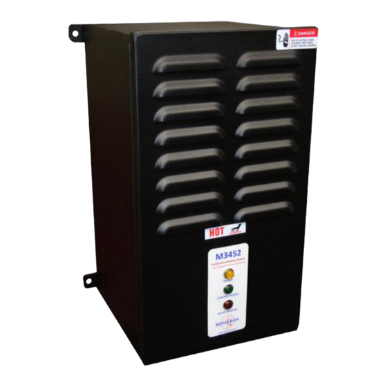
1.1. Who Should Use ......................7 1.2. Purpose and Scope ...................... 7 1.3. Manual Version an d Change Record ................7 Figure 1-1: Typical M3452 Complete Module ................7 1.4. Symbol Conventions Used in this Manual and on Equipment ........8 2. P ................ - Page 5 7.1. Sizing your Braking Requirements ................31 7.1.1. Horsepower to Watts ......................31 7.1.2. Peak Amperage........................31 7.1.3. Ohmic Value ........................31 7.1.4. Duty Cycle ........................... 32 7.1.5. Continuous Rating ....................... 32 7.2. Common Bus Application Note ................... 32 7.3. Bonitron Line Regeneration Modules ................33...
- Page 6 M3452 Complete This page intentionally left blank.
-
Page 7: Introduction
URPOSE AND COPE This manual is a user’s guide for the model M3452 complete braking module. It will provide the user with the necessary information to successfully install, integrate, and use the M3452 complete braking module in a variable frequency AC drive system. -
Page 8: Symbol Conventions Used In This Manual And On Equipment
M3452 Complete 1.4. YMBOL ONVENTIONS SED IN THIS ANUAL AND ON QUIPMENT Earth Ground or Protective Earth AC Voltage DC Voltage DANGER: Electrical hazard - Identifies a statement that indicates a shock or electrocution hazard that must be avoided. DANGER! -
Page 9: Product Description / Features
Dissipating this heat may be impractical in applications with more frequent regeneration. In these applications, the higher cost of the Bonitron M3645 line regen as compared with resistive braking is quickly offset because the regenerated energy, which is returned to the AC line with near unity power factor, can be used to power other equipment. -
Page 10: General Specifications
M3452 Complete ESISTORS The resistor quantity is indicated by a numeric code. Table 2-3: Resistors ATING ESISTOR UANTITY 2 Resistors 3 Resistors 6 Resistors 8 Resistors 9 Resistors HASSIS The chassis code represents the chassis size of the complete braking module. -
Page 11: General Precautions And Safety Warnings
User’s Manual 2.4. ENERAL RECAUTIONS AND AFETY ARNINGS ▪ H I G H V O L T A G E S P R E S E N T ▪ N E V E R A T T E M P T T O O P E R A T E T H I S P R O D U C T W I T H T H E E N C L O S U R E C O V E R O P E N E D DANGER! ▪... - Page 12 M3452 Complete This page intentionally left blank.
-
Page 13: Installation Instructions
• The M3452 must be properly oriented for proper heat flow through the units. • The M3452 must be mounted with the rear surface of the unit to the mounting surface. Unit should be mounted vertically as shown in Figure 3-2. Failure to do so can result in overheating and damage to the unit or surrounding equipment. - Page 14 M3452 Complete • Figure 3-1: Prohibited Mounting Arrangement Figure 3-2: Recommended Placement and Required Minimum Mounting Clearances...
-
Page 15: Wiring And Customer Connections
User’s Manual 3.4. IRING AND USTOMER ONNECTIONS 3.4.1. OWER IRING Only qualified electricians should perform and maintain the interconnection wiring of this product. All wiring should be done in accordance with local codes. WARNING! Wire size should be selected in accordance with local codes, according to the current rating of the braking transistor. -
Page 16: Control Interface Wiring
M3452 Complete Table 3-2: DC Bus Wiring Specifications INIMUM UMBER M3452-L2B-R030 14 AWG CU M3452-L3B-R020 14 AWG CU M3452-L3B-R030 14 AWG CU M3452-L6B-R010 12 AWG CU M3452-L8C-R004 8 AWG CU M3452-L9C-R007 10 AWG CU M3452-L9C-R015 14 AWG CU M3452-H2B-R120 14 AWG CU... - Page 17 User’s Manual Table 3-3: Control Wiring Specifications ORQUE LECTRICAL ERMINAL UNCTION PECIFICATIONS TS1-1 Ready Status NO 220VAC/DC, 100mA Max 5.3 lb-in 5.3 lb-in TS1-2 Ready Status NC 220VAC/DC, 100mA Max 5.3 lb-in TS1-3 Ready Status COM 220VAC/DC, 100mA Max...
-
Page 18: Typical Configurations
M3452 Complete 3.5. YPICAL ONFIGURATIONS Figure 3-4: Field Connections... - Page 19 User’s Manual This page intentionally left blank.
-
Page 20: Operation
4.3. TARTUP Bonitron complete braking modules are designed to be used with stand-alone or common DC bus drive/inverter systems with bus capacitors. When using the Bonitron modules on common bus systems, special considerations may apply. -
Page 21: Startup Procedure And Checks
No adjustments are necessary for this module. All regulation points are factory adjusted and should not be changed in the field. If your module is not functioning properly, refer to the Troubleshooting Section of this manual, or contact Bonitron for assistance. -
Page 22: Maintenance And Troubleshooting
M3452 Complete AINTENANCE AND ROUBLESHOOTING Repairs or modifications to this equipment are to be performed by Bonitron approved personnel only. Any repair or modification to this equipment by personnel not approved by Bonitron will void any warranty remaining on this unit. -
Page 23: Blown Dc Bus Fuse
This usually indicates serious problems exist and proceeding in this manner carries a high risk of creating additional equipment damage! CAUTION Contact Bonitron before changing the fuse. Possible causes for a blown fuse are: • Shorted heatsink IGBT power transistor •... -
Page 24: Module Over-Temp, Or Module Seems Too Hot
M3452 Complete 5.3.6. ODULE OVER TEMP OR MODULE SEEMS TOO HOT It is normal for this module to produce heat. Temperatures of 150°F are not uncommon. If the modules fan is running, and the module is operating properly, it is within normal tolerances. - Page 25 User’s Manual This page intentionally left blank.
-
Page 26: Technical Help - Before You Call
M3452 Complete – 5.4. ECHNICAL BEFORE YOU CALL If technical help is required, please have the following information available when calling: • Serial number of unit • Name of original equipment supplier (if available) • Record the line to line voltage on all 3 phases •... -
Page 27: Ngineering Ata
User’s Manual NGINEERING 6.1. ATINGS HARTS Table 6-1: Model Ratings RAKING OLTAGE UMBER YCLE YCLE M3452-L2B-R030 30.0 M3452-L3B-R020 20.0 M3452-L3B-R030 30.0 M3452-L6B-R010 14.1 18.9 1200 10.0 M3452-L8C-R004 32.0 42.8 1600 M3452-L9C-R007 21.0 28.1 1800 M3452-L9C-R015 12.6 1800 15.0 M3452-H2B-R120 120.0 M3452-H3B-R075 10.1... -
Page 28: Certifications
Further damages could result. Consult Bonitron if this situation arises. If you wish to place fuses in your DC link, coordinate the fuse size with the proper wire size used in your link as per local codes and regulations. -
Page 29: Dimensions And Mechanical Drawings
User’s Manual 6.6. IMENSIONS AND ECHANICAL RAWINGS Figure 6-1: Enclosure Dimensional Outline (Styles “B” & “C”) -
Page 30: Block Diagrams
M3452 Complete 6.7. LOCK IAGRAMS Figure 6-2: Block Diagram... -
Page 31: Pplication Otes
DC bus current. The braking current in the DC bus will be higher than the AC current absorbed from the load. • Because Bonitron braking transistor modules are rated for peak current, determine the peak braking power required. 7.1.1. -
Page 32: Duty Cycle
7.2. OMMON PPLICATION Bonitron dynamic braking transistor modules are designed to be compatible with individual stand-alone inverter/drive systems, or systems that incorporate a common DC bus arrangement. The common DC bus can be composed of multiple inverter/drive sections tied together where all or some of the sections use their respective AC input,... -
Page 33: Bonitron Line Regeneration Modules
Some high power systems also include redundant or back up sections as well. Once power is applied, all Bonitron modules are designed to be sourced from DC buses that have all the bus capacitors present. - Page 34 M3452 Complete NOTES...
- Page 36 D_M3452_CMAN_vCOMPLETEall_05j 07/17/2019 521 Fairground Court ● Nashville, Tennessee 37211 ● FAX (615) 244-2833 ● www.bonitron.com ● info@bonitron.com (615) 244-2825...
Need help?
Do you have a question about the M3452 and is the answer not in the manual?
Questions and answers