bonitron M3452 Reference Manual
K6, k9, k10, m14, t10 chassis
r8eip, r8pdp options
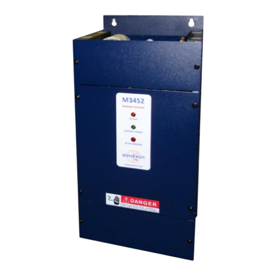
heavy duty braking transistor with ethernet / ip or profibus dp
communications
Hide thumbs
Also See for M3452:
- Customer reference manual (24 pages) ,
- Customer reference manual (80 pages) ,
- Customer reference manual (36 pages)
Table of Contents

Related Manuals for bonitron M3452


Summary of Contents for bonitron M3452
- Page 1 Model M3452 Heavy Duty Braking Transistor with EtherNet / IP or PROFIBUS ® ® Communications K6, K9, K10, M14, T10 Chassis R8EIP, R8PDP Options Customer Reference Manual ● ● Web: www.bonitron.com Tel: 615-244-2825 Email: info@bonitron.com...
- Page 2 Bonitron has seen thousands of products engineered since 1962 and welcomes custom applications. With engineering, production, and testing all in the same facility, Bonitron is able to ensure its products are of the utmost quality and ready to be applied to your application.
- Page 3 RIVE PTIONS In 1975, Bonitron began working with AC inverter drive specialists at synthetic fiber plants to develop speed control systems that could be interfaced with their plant process computers. Ever since, Bonitron has developed AC drive options that solve application issues associated with modern AC variable frequency drives and aid in reducing drive faults.
-
Page 4: Table Of Contents
1.1. Who Should Use ........................... 7 1.2. Purpose and Scope ........................7 1.3. Manual Version and Change Record .................... 7 Figure 1-1: Typical M3452 – R8 ......................... 7 1.4. Symbol Conventions Used in this Manual and on Equipment ............. 8 2. P ......................9... - Page 5 6.6. Resistor Link Length Limits ....................... 54 6.7. Dimensions and Mechanical Drawings ..................55 Figure 6-2: M3452 K6 Chassis Dimensional Outline Drawing ..............55 Figure 6-3: M3452 K9 Chassis Dimensional Outline Drawing ..............56 Figure 6-4: M3452 K10 Chassis Dimensional Outline Drawing ............... 57 Figure 6-5: M3452 M14 Chassis Dimensional Outline Drawing ..............
- Page 6 Figure 6-8: Block Diagram (1600A in M14 Chassis) ................60 7. A ..........................61 PPENDICES 7.1. Application Notes ........................61 7.1.1. Sizing Your Braking Requirements ..................61 7.1.2. Common Bus Application Note ....................63 7.1.3. Bonitron Line Regeneration Modules ..................64...
-
Page 7: Introduction
URPOSE AND COPE This manual is a user’s guide for the Model M3452 dynamic braking transistor module. It will provide the user with the necessary information to successfully install, integrate, and use the M3452 dynamic braking transistor Module in a variable frequency AC drive system. -
Page 8: Symbol Conventions Used In This Manual And On Equipment
M3452 vR8 EIP/PDP 1.4. YMBOL ONVENTIONS SED IN THIS ANUAL AND ON QUIPMENT Earth Ground or Protective Earth AC Voltage DC Voltage DANGER: Electrical hazard - Identifies a statement that indicates a shock or electrocution hazard that must be avoided. -
Page 9: Product Description
User’s Manual RODUCT ESCRIPTION Bonitron M3452 heavy duty braking transistors are used with AC drives to allow full power braking and eliminate overvoltage faults. This permits controlled braking and dramatically shortens motor stopping time. The M3452 works with variable frequency drives (with DC bus connections) to monitor the DC bus. -
Page 10: Part Number Breakdown
M3452 vR8 EIP/PDP Please contact your AC drive distributor or visit our website at www.bonitron.com for more information on these additional products. 2.2. UMBER REAKDOWN Figure 2-1: M3452 Part Number Breakdown R8PDP M3452 AS E O D E L U M B E R... -
Page 11: Table 2-3: Dc Bus Voltage Rating
575 – 600 VAC Line / 940 VDC 690 VAC Line / 1090 VDC” Nxxxx Special (xxxx VDC) Nxxxx is used only for custom trigger levels. Contact Bonitron before specifying Nxxxx. HASSIS The chassis code represents the chassis type and size of the dynamic braking transistor module. -
Page 12: General Specifications
M3452 vR8 EIP/PDP 2.3. ENERAL PECIFICATIONS Table 2-6: General Specifications ARAMETER PECIFICATION 325 – 1090 VDC DC Bus Voltage 200 – 1600 ADC DC Braking Current Single Phase, 115, 230, 380, 460, 575 VAC Control Voltage ±10% 50/60 Hz 70 VA... -
Page 13: General Precautions And Safety Warnings
User’s Manual 2.4. ENERAL RECAUTIONS AND AFETY ARNINGS H IGH VOLTAGES MAY BE PRESENT N EVER ATTEMPT TO SERVICE THIS PRODUCT WITHOUT FIRST DISCONNECTING FROM THE INCOMING POWER AND A LWAYS ALLOW ADEQUATE TIME FOR RESIDUAL VOLTAGES TO DRAIN BEFORE ATTEMPTING SERVICE ... - Page 14 M3452 vR8 EIP/PDP This page intentionally left blank...
-
Page 15: Installation Instructions
DANGER! Proper installation of the model M3452 dynamic brake module should be done following the steps outlined below. Be sure to refer to all other relevant system documentation as these steps are performed. Please direct all installation inquiries that may arise during the installation and start-up of this product to the equipment supplier or system integrator. -
Page 16: Wiring And Customer Connections
If the Bonitron braking transistor is connected to the terminals marked "X" and "-" in Figure 3-10, switching resonances caused by the DC link choke will destroy the braking transistor. If the Bonitron braking transistor is connected between X and Y, the drive will not operate. -
Page 17: I/O Wiring
User’s Manual If the braking transistor is connected to the terminals marked "A" and "B" in Figure 3-10, switching resonances caused by the lack of filter capacitance during precharge will destroy the braking transistor. 3.4.1.2. ESISTOR ONNECTION The polarity of the resistor connections is not important; however, it is critical that the resistor be connected to the proper terminals. -
Page 18: Figure 3-1: Customer Connections In K6 Chassis
M3452 vR8 EIP/PDP Figure 3-1: Customer Connections in K6 Chassis... -
Page 19: Figure 3-2: Customer Connections In K9 Chassis
User’s Manual Figure 3-2: Customer Connections in K9 Chassis... -
Page 20: Figure 3-3: Customer Connections In K10 Chassis
M3452 vR8 EIP/PDP Figure 3-3: Customer Connections in K10 Chassis... -
Page 21: Figure 3-4: Customer Connections In M14 Chassis
User’s Manual Figure 3-4: Customer Connections in M14 Chassis... -
Page 22: Figure 3-5: Customer Connections In T10 Chassis
M3452 vR8 EIP/PDP Figure 3-5: Customer Connections in T10 Chassis DC BUS + DC BUS - RES + RES -... -
Page 23: Typical Configurations
User’s Manual 3.5. YPICAL ONFIGURATIONS Figure 3-6: Master Stand-Alone Hookup Figure 3-7: Master with Slave(s) Hookup... -
Page 24: Figure 3-8: I/O Hookup
M3452 vR8 EIP/PDP Figure 3-8: I/O Hookup Figure 3-9: Equivalent Input/Output Diagrams... -
Page 25: Figure 3-10: Braking Transistor Customer Connections
User’s Manual Figure 3-10: Braking Transistor Customer Connections... - Page 26 M3452 vR8 EIP/PDP This page intentionally left blank...
-
Page 27: Operation
4.1. UNCTIONAL ESCRIPTION The M3452 module controls the bus voltage of a variable frequency drive by transferring energy to a resistor. When the drive’s DC bus voltage exceeds a fixed setpoint, the dynamic braking transistor module’s control electronics turns on an IGBT transistor connecting a resistive load across the DC bus. - Page 28 Do not attempt to use these signals for any purpose other than interconnecting Bonitron M3452 with R7, R7E, or R8 units! Damage may occur to the M3452 as well as to the connected equipment! If monitoring of these signals is desired, see Bonitron model M3452ON.
-
Page 29: Master / Slave Control (200 Amp To 1600 Amp)
User’s Manual (200 A 1600 A 4.2.3. ASTER LAVE ONTROL MP TO Several braking modules can be connected in parallel for current ratings higher than possible with a single module. This method requires that one module be in control of all other modules. This module is considered the Master and the others are slaved to it. -
Page 30: Fieldbus I/O
M3452 vR8 EIP/PDP The Master/Slave Status bit (4.2.4.3.1.1) indicates the operation mode of a module. 4.2.3.2.1. TATIC ASTER Static Master systems have a single module that will always function as the master. For systems that have a static Master module, set the Master bit in the network interface (4.2.4.2.1.4). -
Page 31: Figure 4-1: 3452R8 Memory Map
User’s Manual Figure 4-1: 3452R8 Memory Map INPUT DATA MAP WORD 1 WORD 0 SETPOINT OUTPUT DATA MAP WORD 3 WORD 2 WORD 1 WORD 0 BUS VOLTAGE TEMPERATURE WORD 4 WORD 5-15 FAULT RECORDS DUTY CYCLE 4.2.4.2. NPUTS Words 0-1 of input data are control registers for the braking module. Word 0 is the least significant word. -
Page 32: Figure 4-2 Setpoint Adjustment Range
M3452 vR8 EIP/PDP When the braking unit resets, it clears the faults that are no longer active. This signal operates on a rising edge. 4.2.4.2.1.4. ASTER Setting bit 3 makes the braking unit operate as a master, while clearing the bit represents setting the unit to be a slave. - Page 33 User’s Manual – B 4.2.4.3.1.2. EARTBEAT This bit changes states every 500ms. There is a rising edge every 1 second, and can be used to indicate that the system is still functional and communicating. – B 4.2.4.3.1.3. AULT TATUS This indicates that there are no faults, and that the module is operating properly.
-
Page 34: Fault Modes
M3452 vR8 EIP/PDP 4.2.5. AULT ODES Faults are indicated in two ways. The green Control Power LED on the front of the module will flash, and a fault bit will be set in the Fault Word on the network. When there is any unrecoverable fault, the Status output will open. -
Page 35: Network Configuration
The network configuration depends on the type of network purchased. The M3452-R8 uses the Anybus-S embedded interface controller from HMS networks. Support files for the different networks can be found at www.bonitron.com. Extensive information on setup and operation can be found at www.anybus.com. - Page 36 Connect the network module to a network with a Windows PC. From the Windows PC, run the Anybus IPconfig software, which may be found on the Bonitron website. The program should list any braking kits on the network. Unconfigured modules will have an IP address of 0.0.0.0.
- Page 37 ONFIGURATION The EDS file for the network module may be found by visiting the Bonitron website. Load the EDS file onto your PLC according to your PLC manufacturer’s instructions. Configure both the input and output data ranges to a size of 128 bytes, and the RPI time to 100 If instructed by the PLC for the Assembly Instance, such as the RSLogix 5000, use any non-zero value.
-
Page 38: Figure 4-3: Ethernet / Ip Module Features
M3452 vR8 EIP/PDP Figure 4-3: EtherNet / IP Module Features Link (Activity) Module Status Activity Network Status Legend: Application Connector Ethernet Connector Configuration Switch Anybus Watchdog Status indicators Table 4-2: Ethernet Status Indicators CTIVITY TATE ESCRIPTION Link not sensed Green... -
Page 39: Figure 4-4: Profibus Module Features
User’s Manual 4.2.6.2. ROFIBUS Figure 4-4: PROFIBUS Module Features Profibus Online Fieldbus Profibus Diagnostics Offline PROFIBUS Connector EGEND Termination Switch Node Address Switches Status indicators 4.2.6.2.1. PROFIBUS S TATUS NDICATORS These LEDs indicate run time status and errors to the user. During power up, a LED test sequence is performed according to the EtherNet / IP specification. -
Page 40: Startup
ONFIGURATION The GSD file for the network module may be found by visiting the Bonitron website. Load the GSD file onto your PLC according to your PLC manufacturer’s instructions. Configure both the input and the output data ranges to a size of 128 bytes, and the RPI time to 100 mS. -
Page 41: Operational Adjustments
Refer to the Troubleshooting Section of this manual for more information. For further assistance, contact Bonitron technical support. Once the pre-checks are complete, the drive system can be enabled. Once the drive system is operational, run the motors with light deceleration, and decrease the braking time until the red Active Braking indicator lights. - Page 42 M3452 vR8 EIP/PDP This page intentionally left blank...
-
Page 43: Maintenance And Troubleshooting
Failure to comply may result ATTENTION! in personal injury, death, and / or equipment damage! Feel free to call Bonitron any time the equipment appears to be having problems. 5.3.1. REEN ONTROL POWER LIGHT NOT ILLUMINATED ... -
Page 44: Amber Dc Bus Light Not On
This usually indicates serious problems exist and reenergizing the system can cause significant or catastrophic failure! In most cases, the module will need to be returned for repair. Contact Bonitron before changing the fuse. Possible causes for a blown fuse are: ... -
Page 45: Status Contact Wont Close
If shorted IGBT or IOC faults are reported and will not clear, the module has a fault that needs to be repaired by Bonitron. Contact Bonitron for assistance. If the module is cool and still will not operate, contact Bonitron for assistance or repair. -
Page 46: Drive Trips On Overvoltage
M3452 vR8 EIP/PDP 5.3.8. RIVE TRIPS ON VERVOLTAGE Make sure the DC+ and DC- connections are made directly to the drive system bus. They should not be connected to terminals dedicated to an internal transistor circuit on the inverter. CAUTION! If the drive trips on overvoltage, confirm that the green control power light is on (5.3.1), the status contact is closed (5.3.6), and the amber DC bus light is... -
Page 47: Red Braking Light Stays On All The Time
User’s Manual 5.3.10. RAKING LIGHT STAYS ON ALL THE TIME Make sure the Bus Discharge input is not activated. This causes the braking module to go full on. Extended operation with this input can cause load bank overheating and improper operation. ... -
Page 48: Profibus Fieldbus Offline Light Is Red
M3452 vR8 EIP/PDP PROFIBUS F 5.3.15. IELDBUS FFLINE LIGHT IS RED Make sure there are no duplicate addresses on your PROFIBUS network. Make sure your termination switch is set correctly. PROFIBUS F 5.3.16. IELDBUS IAGNOSTICS LIGHT IS BLINKING Contact Bonitron. -
Page 49: Engineering Data
Table 6-1: Module Ratings: 230 – 240 VAC Drives (375 VDC Setpoint) RAKING RAKING RAKING ONTROL INIMUM ODEL OWER URRENT URRENT USING OLTAGE YCLE ESISTANCE (RMS) UMBER M3452- 115-120 U200LK6 1.90 Ω 100 HP 200 A 200 A 100% FWP-200 M3452- 230-240 L200K6 M3452- 115-120 U300LK6 1.25 Ω... -
Page 50: Table 6-2: Module Ratings: 380 – 415 Vac Drives (620 Vdc Setpoint)
M3452 vR8 EIP/PDP Table 6-2: Module Ratings: 380 – 415 VAC Drives (620 VDC Setpoint) RAKING RAKING RAKING ONTROL INIMUM ODEL OWER URRENT URRENT USING OLTAGE YCLE ESISTANCE (RMS) UMBER M3452- 115-120 U200EK6 3.10 Ω 160 HP 200 A 200 A... -
Page 51: Table 6-3: Module Ratings: 460 – 480 Vac Drives (750 Vdc Setpoint)
Table 6-3: Module Ratings: 460 – 480 VAC Drives (750 VDC Setpoint) RAKING RAKING RAKING ONTROL INIMUM ODEL OWER URRENT URRENT USING OLTAGE YCLE ESISTANCE (RMS) UMBER M3452- 115-120 U200HK6 3.80 Ω 200 HP 200 A 200 A 100% FWP-200 M3452- 460-480 H200K6 M3452- 115-120 U300HK6 2.50 Ω... -
Page 52: Table 6-4: Module Ratings: 575 – 600 Vac Drives (940 Vdc Setpoint)
M3452 vR8 EIP/PDP Table 6-4: Module Ratings: 575 – 600 VAC Drives (940 VDC Setpoint) RAKING RAKING RAKING ONTROL INIMUM ODEL OWER URRENT URRENT USING OLTAGE YCLE ESISTANCE (RMS) UMBER M3452- 115-120 U200CK6 4.70 Ω 250 HP 200 A 200 A... -
Page 53: Watt Loss
Each module (except the 1600 Amp M14 chassis) comes equipped with its own internal DC bus fuse. If the fuse happens to fail, it is not recommended to replace the fuse and reapply power. Further damages could result. Consult Bonitron if this situation arises. -
Page 54: Dc Bus Link Length Limits
M3452 vR8 EIP/PDP DC B 6.5. ENGTH IMITS The distance that the chopper is mounted from the main DC bus filter capacitors within the drive is limited by the amount of inductance in the connection. During switching, the inductance in the DC bus between the chopper and capacitors stores energy that must be absorbed by the snubbing circuit in the chopper. -
Page 55: Dimensions And Mechanical Drawings
User’s Manual 6.7. IMENSIONS AND ECHANICAL RAWINGS Figure 6-2: M3452 K6 Chassis Dimensional Outline Drawing... -
Page 56: Figure 6-3: M3452 K9 Chassis Dimensional Outline Drawing
M3452 vR8 EIP/PDP Figure 6-3: M3452 K9 Chassis Dimensional Outline Drawing... -
Page 57: Figure 6-4: M3452 K10 Chassis Dimensional Outline Drawing
User’s Manual Figure 6-4: M3452 K10 Chassis Dimensional Outline Drawing... -
Page 58: Figure 6-5: M3452 M14 Chassis Dimensional Outline Drawing
M3452 vR8 EIP/PDP Figure 6-5: M3452 M14 Chassis Dimensional Outline Drawing... -
Page 59: Figure 6-6: M3452 T10 Chassis Dimensional Outline Drawing
User’s Manual Figure 6-6: M3452 T10 Chassis Dimensional Outline Drawing... -
Page 60: Block Diagrams
M3452 vR8 EIP/PDP 6.8. LOCK IAGRAMS Figure 6-7: Block Diagram (All 200A thru 1200A and 1600A in T10 Chassis) Figure 6-8: Block Diagram (1600A in M14 Chassis) -
Page 61: Appendices
DC bus current. The braking current in the DC bus will be higher than the AC current absorbed from the load. Because Bonitron braking transistor modules are rated for peak current, determine the peak braking power required. 7.1.1.1. - Page 62 M3452 vR8 EIP/PDP VDC, for 230 VAC systems, it is typically 375 VDC. Refer to your drive manual for specifics. For the above example, the ohmic value would be: ohms 447600 watts brake This value must be verified with the ratings of the braking transistor module selected that it is not less than the “minimum ohmic value”...
-
Page 63: Common Bus Application Note
Some high power systems also include redundant or back up sections as well. Once power is applied, all Bonitron modules are designed to be sourced from DC buses that have all the bus capacitors present. -
Page 64: Bonitron Line Regeneration Modules
ONITRON EGENERATION ODULES The Bonitron line regens return regenerative energy back onto the AC line instead of dissipating the energy as heat in a resistor, and are ideal for applications with high duty cycles, frequent deceleration, or where heat from a resistor may be an issue. - Page 65 User’s Manual NOTES...
- Page 66 M3452 vR8 EIP/PDP...
- Page 68 D_M3452_CMAN_vK6-10M14T10 R8EIP/R8PDPall _02h 09/21/2016 521 Fairground Court ● Nashville, TN 37211 ● USA Tel: (615) 244-2825 ● Fax: (615) 244-2833 ● Web: www.bonitron.com ● Email: info@bonitron.com...
Need help?
Do you have a question about the M3452 and is the answer not in the manual?
Questions and answers