Sign In
Upload
Manuals
Brands
bonitron Manuals
Control Unit
M3452
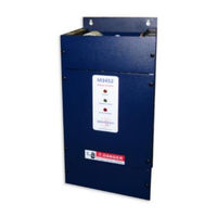
bonitron M3452 Manuals
Manuals and User Guides for bonitron M3452. We have
4
bonitron M3452 manuals available for free PDF download: Customer Reference Manual, Reference Manual
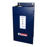
bonitron M3452 Reference Manual (68 pages)
K6, K9, K10, M14, T10 Chassis R8EIP, R8PDP Options Heavy Duty Braking Transistor with EtherNet / IP or PROFIBUS DP Communications
Brand:
bonitron
| Category:
Control Unit
| Size: 2 MB
Table of Contents
Table of Contents
4
1 Introduction
7
Who Should Use
7
Purpose and Scope
7
Manual Version and Change Record
7
Symbol Conventions Used in this Manual and on Equipment
8
2 Product Description
9
Related Products
9
Part Number Breakdown
10
Table 2-3: DC Bus Voltage Rating
11
General Specifications
12
General Precautions and Safety Warnings
13
3 Installation Instructions
15
Product Inspection
15
Site Selection
15
Mounting
15
Wiring and Customer Connections
16
Power Wiring
16
I/O Wiring
17
Table 3-2: I/O Terminal Block Specifications: R8 Control Board
17
Figure 3-1: Customer Connections in K6 Chassis
18
Figure 3-2: Customer Connections in K9 Chassis
19
Figure 3-3: Customer Connections in K10 Chassis
20
Figure 3-4: Customer Connections in M14 Chassis
21
Figure 3-5: Customer Connections in T10 Chassis
22
Typical Configurations
23
Figure 3-6: Master Stand-Alone Hookup
23
Figure 3-8: I/O Hookup
24
Figure 3-10: Braking Transistor Customer Connections
25
4 Operation
27
Functional Description
27
Features
27
Indicators
27
Terminal Strip I/O
27
Master / Slave Control (200 Amp to 1600 Amp)
29
Fieldbus I/O
30
Figure 4-1: 3452R8 Memory Map
31
Figure 4-2 Setpoint Adjustment Range
32
Fault Modes
34
Table 4-1: Fault Conditions Table
34
Network Configuration
35
Figure 4-3: Ethernet / IP Module Features
38
Figure 4-4: PROFIBUS Module Features
39
Startup
40
Pre-Power Checks
40
Operational Adjustments
41
Startup Procedure and Checks
41
5 Maintenance and Troubleshooting
43
Periodic Testing
43
Maintenance Items
43
Troubleshooting
43
Green Control Power Light Not Illuminated
43
Amber DC Bus Light Not on
44
Blown DC Bus Fuse
44
Fan Runs Constantly
44
Fan Doesn't Run
44
Status Contact Wont Close
45
Module Over-Temp, or Module Seems too Hot
45
Drive Trips on Overvoltage
46
Braking Light Flickers
46
Red Braking Light Stays on All the Time
47
Master Unit Appears to Function Properly, but Slave Units Do Not Seem to Follow the Master
47
Ethernet/Ip Link Sensed Light Does Not Turn on
47
Ethernet/Ip Module Status LED Is Solid Red, Flashing Red, or Flashing Green
47
Ethernet/Ip Network Status LED Is Solid Red
47
PROFIBUS Fieldbus Offline Light Is Red
48
PROFIBUS Fieldbus Diagnostics Light Is Blinking
48
Attached Drive will Not Precharge
48
Technical Help - before You Call
48
6 Engineering Data
49
Ngineering Ata
49
Ratings Charts
49
Table 6-1: Module Ratings: 230 – 240 VAC Drives (375 VDC Setpoint)
49
Table 6-2: Module Ratings: 380 – 415 VAC Drives (620 VDC Setpoint)
50
Table 6-3: Module Ratings: 460 – 480 VAC Drives (750 VDC Setpoint)
51
Table 6-4: Module Ratings: 575 – 600 VAC Drives (940 VDC Setpoint)
52
Watt Loss
53
UL 508A Short Circuit Current Rating
53
Fuse/Circuit Breaker Sizing and Rating
53
Table 6-5: Module Ratings: 690VAC Drives (1090 VDC Setpoint)
53
DC Bus Link Length Limits
54
Resistor Link Length Limits
54
Table 6-7: Maximum Inductance for DC Link Cable
54
Dimensions and Mechanical Drawings
55
Figure 6-2: M3452 K6 Chassis Dimensional Outline Drawing
55
Figure 6-3: M3452 K9 Chassis Dimensional Outline Drawing
56
Figure 6-4: M3452 K10 Chassis Dimensional Outline Drawing
57
Figure 6-5: M3452 M14 Chassis Dimensional Outline Drawing
58
Figure 6-6: M3452 T10 Chassis Dimensional Outline Drawing
59
Block Diagrams
60
7 Appendices
61
Application Notes
61
Sizing Your Braking Requirements
61
Common Bus Application Note
63
Bonitron Line Regeneration Modules
64
Advertisement
bonitron M3452 Customer Reference Manual (80 pages)
Brand:
bonitron
| Category:
Control Unit
| Size: 3 MB
Table of Contents
Table of Contents
4
1 Introduction
7
Who Should Use
7
Purpose and Scope
7
Manual Version
7
Symbol Conventions Used in this Manual and on Equipment
8
2 Product Description
9
Related Products
9
Part Number Breakdown
10
General Specifications
12
General Precautions and Safety Warnings
13
3 Installation Instructions
15
Product Inspection
15
Site Selection
15
Mounting
15
Wiring and Customer Connections
16
Power Wiring
16
I/O Wiring
17
DC Control Wiring
17
Typical Configurations
23
4 Operation
27
Functional Description
27
Features
27
Indicators
27
Terminal Strip I/O
28
Master / Slave Control (200 Amp to 1600 Amp)
28
Fieldbus I/O
30
Startup
51
Pre-Power Checks
51
Startup Procedure and Checks
51
Operational Adjustments
52
5 Maintenance and Troubleshooting
53
Periodic Testing
53
Maintenance Items
53
Troubleshooting
53
Green Control Power Light Not Illuminated
53
Amber DC Bus Light Not on
54
Blown DC Bus Fuse
54
Fan Runs Constantly
54
Fan Doesn't Run
54
Control Ready Contacts Wont Close
55
Power Stage Ready Contacts Wont Close
55
Module Over-Temp, or Module Seems too Hot
55
Drive Trips on Overvoltage
56
Red Braking Light Flickers
56
Red Braking Light Stays on All the Time
57
Master Unit Appears to Function Properly, but Slave Units Do Not Seem to Follow the Master
57
Attached Drive will Not Precharge
57
Technical Help - before You Call
57
6 Ngineering Ata
59
Ratings Charts
59
Watt Loss
63
Certifications
63
UL 508A Short Circuit Current Rating
63
Fuse/Circuit Breaker Sizing and Rating
63
DC Bus Link Length Limits
64
Resistor Link Length Limits
65
Dimensions and Mechanical Drawings
65
Block Diagrams
70
7 Appendices
71
Application Notes
71
Sizing Your Braking Requirements
71
Common Bus Application Note
73
Bonitron Line Regeneration Modules
74
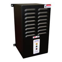
bonitron M3452 Customer Reference Manual (36 pages)
Combination Braking Module with Integrated Transistor and Resistor
Brand:
bonitron
| Category:
Control Unit
| Size: 1 MB
Table of Contents
Table of Contents
4
Introduction
7
Who Should Use
7
Purpose and Scope
7
Manual Version an D Change Record
7
Symbol Conventions Used in this Manual and on Equipment
8
Product Description / Features
9
Related Products
9
Part Number Breakdown
9
General Specifications
10
General Precautions and Safety Warnings
11
Installation Instructions
13
Environment
13
Unpacking
13
Mounting
13
Mounting the M3452
13
Wiring and Customer Connections
15
Power Wiring
15
Control Interface Wiring
16
Typical Configurations
18
Operation
20
Functional Description
20
Features
20
Indicators
20
Startup
20
Pre-Power Checks
20
Startup Procedure and Checks
21
Operational Adjustments
21
Maintenance and Troubleshooting
22
Periodic Testing
22
Maintenance Items
22
Troubleshooting
22
Control Power Light Not Illuminated
22
DC Bus Light Not Illuminated
22
Blown DC Bus Fuse
23
Fan Runs Constantly
23
Fan Doesn't Run
23
Module Over-Temp, or Module Seems too Hot
24
Drive Trips on Overvoltage
24
Braking Light Flickers
24
Braking Light Stays on All the Time
24
Technical Help - before You Call
26
Ngineering Ata
27
Ratings Charts
27
Turn on Voltages
27
Certifications
28
UL 508A Short Circuit Current Rating
28
Fuse/Circuit Breaker Sizing and Rating
28
Dimensions and Mechanical Drawings
29
Block Diagrams
30
Pplication Otes
31
Sizing Your Braking Requirements
31
Horsepower to Watts
31
Peak Amperage
31
Ohmic Value
31
Duty Cycle
32
Continuous Rating
32
Common Bus Application Note
32
Bonitron Line Regeneration Modules
33
Advertisement
bonitron M3452 Customer Reference Manual (24 pages)
Braking Transistor
Brand:
bonitron
| Category:
Circuit breakers
| Size: 0 MB
Table of Contents
Table of Contents
5
1 Introduction
7
Who Should Use
7
Purpose and Scope
7
Manual Version and Change Record
7
2 Roduct Escription
9
Related Products
9
Part Number Breakdown
9
General Specifications
10
General Precautions and Safety Warnings
11
3 Installation Instructions
13
Environment
13
Unpacking
13
Mounting
13
Wiring and Customer Connections
13
Power Wiring
13
Typical Configuration
14
4 Operation
15
Functional Description
15
Features
15
Indicators
15
5 Maintenance and Troubleshooting
17
Troubleshooting
17
Green DC Bus Power Led Does Not Come on
17
Red Active Braking Led Stays on or Flashes During Motoring Operation
17
Drive Trips on Over-Voltage or Self-Limits Its Decel Rate
17
6 Engineering Data
19
Ratings Chart
19
Dimensions and Mechanical Drawings
20
Notes
21
Advertisement
Related Products
bonitron M3452-U200LK6
bonitron M3452-L200K6
bonitron M3452-U300LK6
bonitron M3452-L300K6
bonitron M3452-U600LK6
bonitron M3452-L600K6
bonitron M3452-U800LK9
bonitron M3452-L800K9
bonitron M3452-U1200LK10
bonitron M3452-L1200K10
bonitron Categories
Control Unit
Controller
Test Equipment
Power Supply
Power distribution unit
More bonitron Manuals
Login
Sign In
OR
Sign in with Facebook
Sign in with Google
Upload manual
Upload from disk
Upload from URL