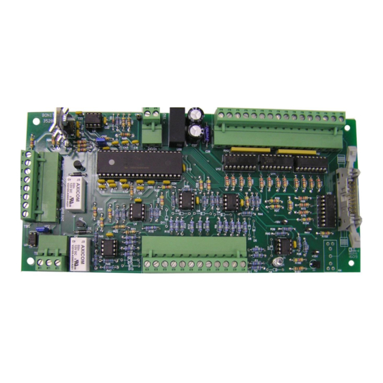
Summary of Contents for bonitron M3528M4
- Page 1 Model M3528M4 Battery Voltage Monitor Module Customer Reference Manual ● ● Web: www.bonitron.com Tel: 615-244-2825 Email: info@bonitron.com...
- Page 2 Bonitron has seen thousands of products engineered since 1962 and welcomes custom applications. With engineering, production, and testing all in the same facility, Bonitron is able to ensure its products are of the utmost quality and ready to be applied to your application.
- Page 3 RIVE PTIONS In 1975, Bonitron began working with AC inverter drive specialists at synthetic fiber plants to develop speed control systems that could be interfaced with their plant process computers. Ever since, Bonitron has developed AC drive options that solve application issues associated with modern AC variable frequency drives and aid in reducing drive faults.
- Page 4 M3528M4 This page intentionally left blank...
-
Page 5: Table Of Contents
5.4. Battery Undervoltage ........................19 5.5. Over Temperature ........................19 6. E ........................21 NGINEERING 6.1. Ratings ............................21 6.2. Dimensions and Mechanical Drawings ..................21 Figure 6-1: M3528M4 Dimensional Outline Drawing ................21 Figure 6-2: M3528D4 Battery Monitoring Panel Mounting Information ..........21... - Page 6 M3528M4 This page intentionally left blank...
-
Page 7: Introduction
1.2. URPOSE AND COPE This manual is a user’s guide for the Model M3528M4 Battery Voltage Monitor Module. It will provide the user with the necessary information to successfully install, integrate, and use the M3528M4. In the event of any conflict between this document and any publication and/or documentation related to the DC storage system, the latter shall have precedence. - Page 8 M3528M4 This page intentionally left blank...
-
Page 9: Product Description
Batteries, capacitors, and any other system can be damaged by the voltage across them rising too high. The M3528M4 voltage monitor is designed to monitor DC voltage levels and signal the user if the voltage departs a set range. -
Page 10: General Precautions And Safety Warnings
M3528M4 2.4. ENERAL RECAUTIONS AND AFETY ARNINGS H I G H V O L T A G E S M A Y B E P R E S E N T F AI L U R E H E E D... -
Page 11: Installation Instructions
Wire types and sizes should be chosen in accordance with national and local electrical codes to meet the voltage and current levels present for your application. Figure 3-1 shows a typical interconnection of the M3528M4 with a DC voltage source and I/O signals. - Page 12 M3528M4 Figure 3-1: Typical Interconnection Dwg: 090113 Rev: 20090417...
-
Page 13: Power Wiring
User’s Manual Only qualified electricians should perform and maintain the interconnection wiring of this product. All wiring should be done in accordance with National CAUTION! Electrical Code or equivalent regulations. 3.3.1. OWER IRING Internal or external 24V 200mA. I/O W 3.3.2. - Page 14 M3528M4 Table 3-3: Wiring Specifications TB3 LECTRICAL ERMINAL UNCTION ORQUE PECIFICATIONS TB3-1 Battery 1 status signal Open Collector 24V 150mA .5 Nm Battery 2 status signal Open Collector 24V 150mA TB3-2 .5 Nm TB3-3 Battery 3 status signal Open Collector 24V 150mA .5 Nm...
-
Page 15: Operation
There are remote monitoring outputs for connection to a PLC or other supervisory system, as well as relay outputs to allow for control functions of ancillary equipment. The unit has a ribbon connector that can be used to drive the Bonitron M3528D4 display panel for remote mounting of indicators. -
Page 16: Connectors
M3528M4 Output relays open. The Fault will latch until the unit cools down and the user pushes the reset button on the front panel. 4.2.2. ONNECTORS TB1 -1 (F 4.2.2.1. This terminal connects the input side of the fuse for monitoring. A voltage higher than 10VDC on this pin between TB1-1 and TB1-12 will indicate a good fuse. -
Page 17: Jumpers
User’s Manual This relay opens when any battery has an Overvoltage, a Blown Fuse, or Overtemperature. The relay is rated for 250 VDC, 230VAC, 3A maximum. TB5 - 3&4 (S 4.2.2.13. TATUS IGNAL UTPUT Same as TB5-1&2. TB5 - 5&6 (U 4.2.2.14. -
Page 18: Ribbon Connector
M3528M4 4.2.4. IBBON ONNECTOR The unit has a ribbon connector that can be used with the Bonitron M3528D4 display panel. The indicators on the front panel that will show basic status information for the supply. 4.2.4.1. ATTERY TATUS The Battery Status LEDs are 10 LEDs indicate which battery reaches an Overvoltage or Undervoltage limit. -
Page 19: Troubleshooting
Repairs or modifications to this equipment are to be performed by Bonitron approved personnel only. Any repair or modification to this equipment by personnel not approved by Bonitron will void any warranty remaining on this unit. - Page 20 M3528M4 This page intentionally left blank...
-
Page 21: Engineering Data
User’s Manual NGINEERING 6.1. ATINGS Power Supply tolerance: 24VDC±10%. 6.2. IMENSIONS AND ECHANICAL RAWINGS Figure 6-1: M3528M4 Dimensional Outline Drawing Figure 6-2: M3528D4 Battery Monitoring Panel Mounting Information Dwgs: 090117 and 090118 Rev: 20121217... - Page 22 M3528M4 NOTES...
- Page 24 D3528M4_CMAN_VALL_00b 04/04/2014 521 Fairground Court ● Nashville, Tennessee 37211 (615) 244-2825 ● FAX (615) 244-2833 ● www.bonitron.com...


Need help?
Do you have a question about the M3528M4 and is the answer not in the manual?
Questions and answers