Table of Contents
Advertisement
Quick Links
Installation and Maintenance Manual
®
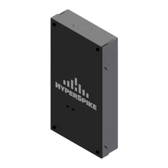
HyperSpike
MPA-400
WARNING: This document contains technical data and/or technology whose export is restricted by the United States Arms Export Control Act (AECA), International Traffic in
Arms Regulations (ITAR) and/or Export Administration Act of 1979 (EAR), as amended. It may not be transferred to any foreign national, wherever located, without prior written
authorization from the United States government. This information may not be resold, transferred, retransferred, reexported, transshipped on a non-continuous voyage, or
otherwise be disposed of in any country, either in its original form or after being revised or incorporated into any other documents, without the prior written approval from the United
States government or as otherwise authorized by the United States law and regulations. Violations of these export control laws are subject to severe criminal penalties.
ultra-hyperspike
MPA400-MAN-IPFORMER Rev B | Copyright © 2020 USSI
Advertisement
Table of Contents

Related Manuals for Ultra electronics HyperSpike MPA-400


Summary of Contents for Ultra electronics HyperSpike MPA-400
- Page 1 Installation and Maintenance Manual ® HyperSpike MPA-400 WARNING: This document contains technical data and/or technology whose export is restricted by the United States Arms Export Control Act (AECA), International Traffic in Arms Regulations (ITAR) and/or Export Administration Act of 1979 (EAR), as amended. It may not be transferred to any foreign national, wherever located, without prior written authorization from the United States government.
- Page 2 DISCLAIMER AND WARNING The information in this manual affects your safety and your legal rights and responsibilities. Read this entire manual carefully to ensure proper configuration before use. Failure to read and follow instructions and warnings in this manual may result in serious injury to yourself or others, or damage to other objects in the vicinity.
-
Page 3: Table Of Contents
CONTENTS 1. Overview ..............................4 1.1 Compatibility ............................4 1.2 Description ............................4 1.3 Identification ............................5 1.4 Features .............................. 5 1.5 Specifications ............................7 2. Mounting the MPA400 System ......................... 8 2.1 Mounting ............................. 8 3. Making Connections ..........................9 ®... -
Page 4: Overview
IMPORTANT The HyperSpike MPA400 contains parts and assemblies susceptible to damage by electrostatic discharge (ESD). Use proper grounding techniques when working in the module. 1. OVERVIEW 1.1 Compatibility The HyperSpike MPA400 system interfaces with the following HyperSpike direct drive speakers. 90243A-802-XX –... -
Page 5: Identification
1.3 Identification To aid future troubleshooting and support, please record the following specifics about your installation: Purchase Date: ________________________________________ Speaker Model Number: ________________________________________ Speaker Serial Number: ________________________________________ MPA400 Serial Number: ________________________________________ MPA400 User Number: ________________________________________ MPA400 RID Number ________________________________________ 1.4 Features The MPA400 comes in a wall mounted housing that includes ½”... - Page 6 ® The inside of the housing contains a sophisticated CCA to power HyperSpike and other direct drive audio speakers using PoE+ or an optional AC to DC power supply. Knockouts (1/2” trade size) are available on each side of the housing for all external connections (speaker out, PoE+, AC power input). Figure 2: Internal Housing Detail ultra-hyperspike MPA400-MAN-IPFORMER Rev B | Copyright ©...
-
Page 7: Specifications
1.5 Specifications 4.7” W x 8.8” H x 1.6” D Dimensions (119.4mm W x 223.5mm H x 40.6mm D) Weight without Batteries < 2 lbs. Enclosure NEMA 1 / IP54 Temperature Range 0°C to 50°C Line Wave and TCPA-10 (Direct Drive) speakers up Compatible Speakers to 40W Power (Auto Switching) -
Page 8: Mounting The Mpa400 System
2. MOUNTING THE MPA400 SYSTEM 2.1 Mounting The MPA400 uses a NEMA 1 housing and is to be located indoors in a climate-controlled building. When mounting the housing, note the CCA orientation in the housing. It is recommended that the housing is mounted such that connections are made on the same end as the connectors on the CCA. -
Page 9: Making Connections
3. MAKING CONNECTIONS The MPA400 system is configured such that connections are made through the conduit knockouts. It is recommended that connections are made on the same end as the connectors on the CCA. See Figure 4 for reference. Although connections can be made in other locations, appropriate space and wire routing mechanisms are not provided when routing into other locations. -
Page 10: Connecting Hyperspike Speakers
® 3.1 Connecting HyperSpike Speakers The MPA400 includes a 4-position output connector that will accept 16-26 AWG wire. See Figure 5 for speaker output connections. Install positive (+) speaker wire(s) in pin 3 (red wire shown) and negative speaker wire(s) in pin 4 (black wire shown). Note: Wire colors are for reference only, see speaker manual for wire color and polarity. -
Page 11: Connecting To A Wired Poe Network
3.2 Connecting to a Wired PoE Network The MPA400 has a standard RJ45 network jack and requires a standard Ethernet cable (CAT5e or better). If optional 24 VDC power is not used, the network connection will need to provide PoE+ or 4PPoE power. Figure 6 - Network Connection 3.3 Connecting Optional 24VDC Power Supply The MPA400 includes a 2-position input connector that will accept 16-26 AWG wire. -
Page 12: Commissioning
4. COMMISSIONING 4.1 Post Installation System Check 1) Check to ensure all wiring connections are secure: Speaker wiring (check polarity of each speaker connection) Network Connection 24VDC Power (Optional) 2) Verify Network connections and that a DHCP Server is available within the network. 4.2 Power-up Sequence 1) Enable Power 2) MPA400 will acquire an IP Address and announce it on the speaker output. - Page 13 Please refer to the help description in the user interface to properly configure your sources. Please refer to the help description in the user interface to properly configure your sources. Individual Volume can be set for each of the sources. Figure 8 - Sources Page 3) Prioritize you Sources Multiple sources can be configured at the same time and are played according to their given priority.
- Page 14 Example of a Priority System • Priority 3: HTTP Radio Stream playing Background music. • Priority 2: RTP Streams playing adds over the background music. Background music will stop as soon as the RTP stream is present • Priority 1: SIP call playing emergency calls. Background music or add will be stopped as soon as SIP call is present.
-
Page 15: Security Settings
Figure 10 - Settings Page 6) Monitor the MPA400 The "Source Status" page on the web interface will show you the actual status of the sources of the MPA400. Every source status also includes a counter indicating how many times the actual source has been played. -
Page 16: Network Settings
• Update Function: Enable or disable the possibility to update the device from web user interface (button grayed out) 4.5 Network Settings In the MPA400 Settings page there are parameters used to configure your device with the desired network settings. To set the network settings: 1) Wire your MPA400 to a network where a DHCP server is available and switch it on, hear the IP announced over the audio output (SonicIP®... -
Page 17: Restore Factory Defaults
Figure 13 - Update Page Once the package is downloaded: 1) Connect to the MPA400’s web user interface 2) Navigate to UPDATE from the top bar 3) Click on "Please click here to start the update" 4) In the following page click on "Browse", locate the TAR package you just downloaded on your PC and open it 5) Click on "Upload"... - Page 18 Soft Reset A soft reset restores all parameters except the network settings. To reset the device including network settings perform a Hard Reset. 1) Connect to the web user interface of the MPA400 and navigate to the DEFAULTS tab. 2) Click on Reset Factory Defaults to perform a reset of the device. Figure 14 - Defaults Page Hard Reset A hard reset restores all values and settings on the MPA400.
-
Page 19: Health And Status Monitoring
5. HEALTH AND STATUS MONITORING 5.1 Status LEDs The MPA400 has 2 LEDs visible form front of the housing. These LEDs provide system and applications status. See Tables 5 and 6 for status descriptions Figure 15 - LED Status Table 3: System Status LED Color LED Status Status Description... -
Page 20: Maintenance And Troubleshooting Guide
6. MAINTENANCE AND TROUBLESHOOTING GUIDE 6.1 Recommended Maintenance On a regular basis, check the system: • Check for vandalism or natural damage. • Check speaker wiring for frays, cuts, and kinks. • Perform an operational test. 6.2 Troubleshooting Guide • For amplifier module related issues: Refer to Section 5.1 to verify system status. -
Page 21: Warranty
Upon receipt of the returned product(s), Ultra Electronics – USSI will repair or replace any and all product(s) at its discretion. Ultra Electronics – USSI will not issue a credit for product(s) returned through the Return Authorization process.
Need help?
Do you have a question about the HyperSpike MPA-400 and is the answer not in the manual?
Questions and answers