Advertisement
Quick Links
BEU SYSTEM PRACTICES
AT& TCo Standard
GENERAL
1.
This section contains information on the lOA
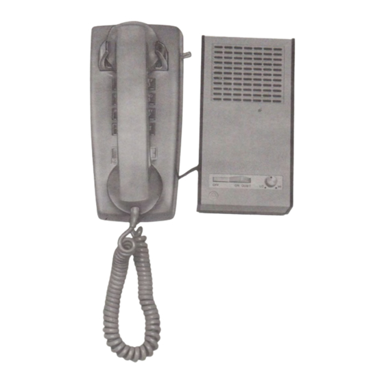
1.01
transmitter-receiver (TELEHELPER speak
erphone). The TELEHELPER speakerphone (Fig. 1)
is a one piece rectangular shaped unit referred to in
this section as speakerphone. The speakerphone is
equipped with modular jacks and can be readily con
nected to residential single line modular rotary or
TOUCH-TONEt dial desk or wall telephone sets.
1.02
Whenever this section is reissued, the reason
for reissue will be listed in this paragraph.
1.03
A D-181062 Kit of Parts is required when the
speakerphone is to be wall mounted in con
junction with a wall telephone set (Fig. 2).
Note:
use with multiline or business telephones and
cannot be used on party line service.
2.
IDENTIFICATION
The speakerphone is available only with a
2.01
dark brown (-104) base and an ivory (-50)
cover (Fig. 3). The base contains a sliding battery and
cord connections cover (Fig. 5). Under this cover are
two compartments; the larger one is for a standard
9-volt alkaline battery, the other contains two modu
lar jacks. The eight conductor jack is labeled LINE,
the six conductor jack is labeled PHONE (Fig. 5).
2.02
Design Features:
Modular cord connected
•
Compatible with both rotary and TOUCH
•
TONE service
*Trademark of American Telephone and Telegraph Company.
tRegistered Trademark of American Telephone and Telegraph
Company.
BSP
512-750-100-i01-i01_198·01.jpg
Scanned by Frank Harrell, (Cowboy Frank) Castle Rock, Colorado Feb 23,2012 22:55:31
"TELEHELPER*" SPEAKERPHONE SYSTEM
IDENTIFICATION, INSTALLATION, CONNECTION, OPERATION,
The speakerphone is not intended for
Bell System except under written agreement
AND MAINTENANCE
•
•
•
•
•
•
2.03
•
•
•
•
•
NOTICE
Not for use or disclosure outside the
Printed in U.S.A.
SECTION
Battery powered voice actuated transmit and
receive switching
Line powered receive amplifier
No ac power required
Weak battery alarm
Battery interlock (battery not in circuit un
less battery and cord connection cover is
closed)
Built in polarity guard.
Operational Features:
This speakerphone is not compatible
with all network facilities due to
limited available loop current, and
may not function properly in all
cases. When connected to facilities,
such as analog loop carrier systems
(SLC-1 and SLC-8 type) and long
loops (over 1300 ohms) the volume
and fidelity of the receive speech
from the loudspeaker may not be
acceptable.
Both dialing and ringer alerting accom-.
plished through the associated telephone set
Speakerphone can be used for answer only
(no associated telephone set)
All nonassociated telephone sets on same line
must be a minimum of 10 feet from speaker
phone to prevent feedback
Dialing on associated telephone set can only
be accomplished with speakerphone in the
OFF position
With speakerphone switch in the ON position
associated telephone set is disconnected
512-750-100
Issue
1,
August
1981
Page 1
Advertisement

Subscribe to Our Youtube Channel
Related Manuals for Bell System Practices TELEHELPER

Summary of Contents for Bell System Practices TELEHELPER
- Page 1 This section contains information on the lOA 1.01 Line powered receive amplifier transmitter-receiver (TELEHELPER speak • erphone). The TELEHELPER speakerphone (Fig. 1) No ac power required is a one piece rectangular shaped unit referred to in • this section as speakerphone. The speakerphone is Weak battery alarm •...
- Page 3 SECTION 5 12-750- 100 PHONEMOUNT 7308 AOAPTER SCREWS SPEAKERPHONE WALL MOUNT ADAPTER Fig. 2-D- 1 8 1 062 Kit of Parts Used When Wall Mounting Speakerphone Cord, D4BU-29 (2-foot) • accept a D4BU mounting cord. The telephone set to be associated with speakerphone must also be modu Cord, Mounting, D6AA-87 •...
- Page 5 COVER HOLD DOWN SCREWS CORD SLOTS Fig. 4-Bottom of TELEHELPER Speakerphone to the microphone port (Fig. 4). Also avoid lo Plug one end of the D8AA mounting cord into • the larger (8-conductor) jack on the 304A cating in noisy locations and near sources of heat and dust.
- Page 6 COVER VOLT ALKALINE BATTERY Fig. 5-Bottom View of The TELEHELPER Speakerphone With Battery and Cord Con nections Cover Removed utilizing the D-180882 Kit of Parts unplug the speakerphone which will provide a hard surface D8AA mounting cord from the 304A adapter.
- Page 7 ISS 1, SECTION S 12-750-100 LINE "" "" ""' """" INTO LINE JACK IN ''TELEHELPER" SPEAKERPHONE Fig. 6- Recommended Installation for Single Line Modular Desk Type Telephone Set (1) Place template (Fig. 8) over 630A4 connecting ment. Replace battery and cord connections cover.
-
Page 8: Installation Test
SECTION 5 12-750-100 DBAA MTG CORD PLUGGED INTO LINE JACK IN 10A TELEPH ONE SET •' TELEHELPER '/ SPEAKERPHONE Fig. 7- 0ptionallnstallation for Single Line Modular Desk Type Telephone Set With 180882 Kit of Parts Tighten the screws firmly but avoid Check telephone set transmission and recep... -
Page 9: Operation
ISS 1, SECTION 5 1 2-750- 1 00 When the speakerphone switch is operated to distant party is prevented allowing a private • the ON position the telephone set should be off-line conversation at the speakerphone disconnected from circuit and ringing or location. - Page 10 "' USE THIS SIDE FOR LEFT HANDED SPE A KERPHONE MOUNTING ..� ..� L O C ATE EXISTING WA LL JACK IN THIS OP ENING ROTARY TR ADITIONAL TAM-16® GHll l!l lll l!l l'll l!llll ll l [!)111 1!1 NOTE: LA Y O U T FOR RIGHT HANDED...
- Page 12 TELEHELPER SPEAKERPHONE WITH BATTERY AND CORD CONNECTIONS COVER REMOVED Fig. 10-7308 Phonemount and Speakerphone Wall Adapter Cords Plugged Into Jacks in The TELEHELPER Speakerphone Page 12 SSP S12-750-100-i01-i01_198·12.jpg Scanned by Frank Harrel!, {Cowboy Frank) Castle Rock, Colorado feb 23,2012 23:00:27...
- Page 13 730B PHONEMOUNT APPROXIMATE 730B CORD DRESS PHONEMOUNT CORD Fig. 11- Approximate Cord Dress of 7308 Phonemount Cord With Telephone Location Right of TELEHELPER Speakerphone Page 13 SSP S12-750-100-i01-i01_198·13.jpg Scanned by Frank Harrel!, {Cowboy Frank) Castle Rock, Colorado feb 23,2012 23:00:47...
- Page 14 SECTION 512-750-100 7308 PHONEMOUNT PHONEMOUNT 7308 CORD 12- Approximate Cord Dress of 7308 Phonemount Cord With Telephone Location Left of TELEHELPER Speakerphone Page 14 Scanned by Frank Harrell. (Cowboy Frank) Castle Rock, Colorado Feb 23,2012 23:01:02 BSP 512-750-100·i01·101 _198-14.jpg...
- Page 15 WALL MOUNT ADAPTER CONNECTED TELEHELPER SPEAKERPHONE Fig. 13- Rear View of TELEHELPER Speakerphone With Wall Mount Adapter Attached and 2S54-Type Telephone Connected on 7308 Phonemount Page 15 15 Pages BSP 512-750-100-i01-i01_198-15.jpg Scanned by Frank Harrell, {Cowboy Frank) Ca!.Ue Rock, Colorado...
Need help?
Do you have a question about the TELEHELPER and is the answer not in the manual?
Questions and answers