
Related Manuals for Energetiq LDLS EQ-9


Summary of Contents for Energetiq LDLS EQ-9
- Page 1 Model EQ-9 ™ LDLS Laser-Driven Light Source Operation Manual Revision 3 April 2018 Part Number DOC-7173...
- Page 2 Energetiq and shall not be reproduced in whole or in part without the written consent of Energetiq. The content of this manual is subject to change without notice.
- Page 3 EU Declaration of Conformity...
-
Page 4: Table Of Contents
TABLE OF CONTENTS Chapter 1 ..............................1 General Information ........................... 1 Safety ............................... 1 Chapter 2 ..............................6 Description ............................6 General ............................6 Specifications ..........................7 System Description ........................10 Power Supply Controller ......................10 Lamp House ..........................13 Chapter 3 .............................. -
Page 5: Chapter 1
C h a p t e r 1 GENERAL INFORMATION Safety WARNING This unit emits ultraviolet (UV) radiation that is harmful to humans. Avoid exposure to the direct or reflected output beam. Make certain that the appropriate output beam shields and optics are in place prior to energizing the unit. - Page 6 There are no user-serviceable parts inside the EQ-9. For any problems encountered during operation, please contact Energetiq Technology for assistance. If there is a component failure, do not attempt to open the Power Supply Controller or Lamp House enclosure of the EQ-9.
- Page 7 Lamp House or Power Supply Controller enclosure. The unit must not be operated if the covers are removed or it is defective in any way. Contact Energetiq if any problems with the equipment are suspected. DOC-7173 Rev. 3 EQ-9 Operation Manual...
- Page 8 Labels and Safety Notification The following safety labels appear on the product. Figure 1 shows the location of each label on the EQ-9 system. UV Hazard warning label – indicates hazardous levels of UV light are present. Manufacturer’s identification label – gives the manufacturer’s name, the model number, serial number, and date of manufacture of the equipment.
- Page 9 UV Hazard Non-interlocked Manufacturer’s Warning Label Housing Label Identification label Explanatory Label Certification Label Figure 1: Safety Label Locations Safety Interlocks The EQ-9 is equipped with interlocks to prevent operation of the device when any of the following conditions are present: 1.
-
Page 10: Chapter 2
C h a p t e r 2 DESCRIPTION General The EQ-9 is a broad-band lamp system for use in a wide variety of applications. The lamp produces high brightness, broad-band light from DUV wavelengths through visible and beyond. The output is very stable, and has a long lifetime before any service is required. A simple control interface ensures ease of use. -
Page 11: Specifications
Specifications Optical Performance Typical output spectrum: see Figure 2. Relative EQ-9 Spectral Radiant Flux (Typical) 200 250 300 350 400 450 500 550 600 650 700 750 800 850 Wavelength (nm) Figure 2: Typical Output Spectrum Physical Specifications Dimensions (H x W x D) ... - Page 12 Utility Requirements Electrical: 12VDC, 140W Cooling: Fan (30 CFM forced air cooling) Purge gas (optional): clean dry nitrogen, filtered (5um 20 psig (0.14 MPa) supply pressure) Remote Interface Digital Inputs Type: Optocoupler LED Logic: Active High ...
- Page 13 Recommended Cooling Direction [30 CFM] Figure 3: Recommended Cooling Configuration Environmental Requirements Operating Ambient temperature: 15–30°C (with 30 CFM forced air cooling) Relative Humidity: non-condensing, 80% max. for temperatures up to 31°C, decreasing linearly to 50% max. at 40°C. ...
-
Page 14: System Description
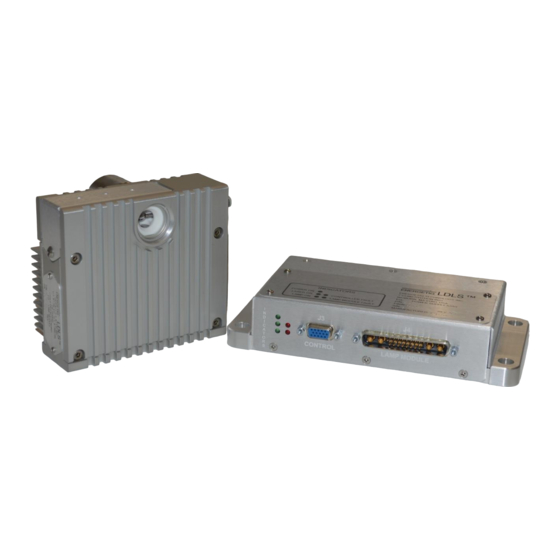
House, Controller to Lamp house interconnect cable (not shown). Power and I/O interface connections (also not shown) are either provided by the user or by Energetiq upon request. The following sections provide descriptions of the system components and controls, and give an overview of their functions. - Page 15 Laser power supply Thermo-electric cooler control system for laser Control electronics Status indicator LEDs Interface connectors External features (refer to Figure ): Status Indicator LEDs These five LEDs indicate the system status. The function of these indicators is shown below in Table 2.
- Page 16 Provides access to control and status signals. See Chapter 3 for pin assignments and functions. This is the only operator interface to the EQ-9 – there are no local controls. Energetiq offers the EQ-99-RC Remote Control Module which connects to the Input/Output connector of the EQ-9 or EQ-99 and provides a means of local control.
-
Page 17: Lamp House
Lamp House The Lamp House assembly contains: Lamp Igniter Laser Thermoelectric cooler IR pumping optics Output windows Laser ON indicator Interface connectors Lamp Window (front) Laser ON Indicator Purge Gas Port Control Connector (to Controller) Figure 5: Lamp House Assembly... - Page 18 Lamp Windows The lamp windows at the optical output provide protection from the high pressure bulb inside the Lamp House. An internally-threaded SM1 adapter is provided for easy connection of optical hardware. Nitrogen Purge Inlet This is the inlet fitting for nitrogen purge gas. Purge gas is optional but is recommended for best performance when a deep UV bulb is provided.
-
Page 19: Chapter 3
1) I/O cable with 15 pin D- connector at each end 1) DC power supply with custom connector If any part is missing or appears damaged, contact Energetiq immediately. Do not attempt to substitute any parts. There are no user-serviceable parts inside the EQ-9 Lamp House or Power Supply Controller unit. - Page 20 Power can be provided via a customer provided 12VDC power supply. The connector on the EQ-9 is a jack screw secured connector. This protects from accidental removal of power if the power cable is pulled. Connect to a 12VDC source as follows: Connector FCI DA3W3SA00LF Pin A1...
- Page 21 Figure 6: Lamp House mechanical layout DOC-7173 Rev. 3 EQ-9 Operation Manual...
- Page 22 Figure 7: Lamp House Output Window Detail A EQ-9 Operation Manual DOC-7173 Rev. 3...
- Page 23 Figure 8: Power Supply Controller mechanical layout DOC-7173 Rev. 3 EQ-9 Operation Manual...
- Page 24 Signal Connections The EQ-9 is controlled through the remote I/O connector. Table 3 gives the pin assignments and functions for this interface. Connect to the user’s control system using a suitable cable. Mating connector is a standard high-density 15-pin d- sub male (for example, Amp part no.
- Page 25 EQ-9 5V Power Pin 5 Isolated 0.1uF 5VDC supply Contact or Inputs solid-state switch Pins 11, 12, 13 0.1uF Outputs Load Pins 1, 2, 3, 4 5V Return Pins 6, 7, 8, 9 EQ-9 5V Power Pin 5 Isolated 0.1uF 5VDC supply Contact or Inputs...
-
Page 26: Rs-485 Serial Interface
RS-485 Serial Interface General This specification defines the commands and functions available for customer use via the EQ- 9-HP RS-485 port. The interface is derived from the EQ-400 customer interface, with some changes to the system status readback. The RS-485 port will continue to support Logwatch as usual. Hardware Hardware configuration is as follows: Half-duplex (2-wire) RS-485, standard 9-pin male d-sub connector, 120 ohm termination across the data lines. - Page 27 See below for bit mapping. Displays a help menu listing the available EQ9-HP firmware vXXX build commands date mm/dd/yy (c) Energetiq Technology, Inc. Inc/Dec laser pwr (by 0.5% full scale) Q Query laser pwr setpoint F Reset laser pwr to default...
- Page 28 System status word Bit # Definition 0 (LSB) Fault status: 1 = one or more faults present, 0 = no faults Laser status: 1 = on, 0 = off Lamp status: 1 = on, 0 = off Laser temperature: 1 = overtemperature, 0 = OK Reserved –...
-
Page 29: Installation Procedure
Operating the source without any output target or beam transport is not recommended, and may lead to unsafe operating conditions. Consult Energetiq for applications information and suggested configurations. The Lamp House should be mounted in the orientation shown in Figure 4, with the output windows on the side and the bulb oriented horizontally. -
Page 30: Chapter 4
This is very unusual. However, if this occurs, turn the OPERATE switch to the OFF position (down) and begin at Step 1 again. If this occurs multiple times, contact Energetiq service Stopping To turn the LAMP off, simply turn the OPERATE Switch to the OFF position. If the lamp will not be used for some time, the 12VDC supply can be turned off. - Page 31 POWER OK LASER ON CONTROLLER FAULT LAMP ON LAMPHOUSE FAULT Figure 10. Identification of Indicator LED’s on Control Unit DOC-7173 Rev. 3 EQ-9 Operation Manual...
-
Page 32: Chapter 5
C h a p t e r 5 TROUBLESHOOTING Fault Indicator Block Diagram Laser On Lamp Fault Controller Fault De-Asserted 150 sec Lamp On Asserted after Operate Asserted De-Asserted Command (pin 3 on remote) (pin 4 on remote) (pin 1 on remote) (pin 2 on remote) Signal Available on User Interface Internal Logic That Generates Signal... - Page 33 If all of the interlocks are OK and either the lamp or controller interlock faults will not clear, please contact the factory. Condition: Lamp fails to ignite after several tries. Action Contact Energetiq. DOC-7173 Rev. 3 EQ-9 Operation Manual...
-
Page 34: Revision Control
A p p e n d i x A REVISION CONTROL Version Number Modified By Modifications Made Date Modified Rev. 3 M. Steinberg Updated CE Mark, Logo, Page April 2018 footer format, added RS-485 information, added Appendix A EQ-9 Operation Manual DOC-7173 Rev. - Page 35 Energetiq and shall not be reproduced in whole or in part without the written consent of Energetiq. The content of this manual is subject to change without notice.
Need help?
Do you have a question about the LDLS EQ-9 and is the answer not in the manual?
Questions and answers