Advertisement
Quick Links
Advertisement

Related Manuals for Kogan FORTIS SK-400


Summary of Contents for Kogan FORTIS SK-400
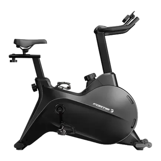
- Page 1 MAGNETIC FLYWHEEL SPIN BIKE (SK-400) FSMFWSK400A...
-
Page 3: Safety And Warnings
Always use the equipment as intended. If you find any defective components while assembling or checking the equipment, or if you hear any unusual noises coming from the equipment during exercise, cease use immediately and contact help.kogan.com for assistance. Do not use until resolved. - Page 4 Operating temperature: 0 - 40 °C • Storage temperature: -10 - 60°C • This appliance contains no user-serviceable parts. If it suffers any failure or damage, cease use immediately and contact help.kogan.com • This equipment is designed and intended for indoor use only.
- Page 5 OVERVIEW...
- Page 6 Parts number/name Specifications Parts number/name Specifications Main Frame Tension knob 58.5 x 57.8 x 5.8 bracket Handlebar Post M6 x H6 x S10 Axle Brake rod Φ8 x 93 x M8 x 70 Magnetic Screw M6 x 16 x S5 Plate 12.5 x 12.5 x 3.0 Front Stabiliser...
- Page 7 Parts number/name Specifications Parts number/name Specifications Crank hole Idle pulley Ф41 x Ф33 x 24 Φ83 x Φ36 x 11 cover Bolt Pedal R HD_201B 9/16 U bracket 30 x 10 x 1.5 Pedal L HD_201B 9/16 Bolt M6 x H6 x S10 Screw ST4.2 x 19 M6 x 8 x Φ12...
- Page 8 ASSEMBLY Step 1: Attach the Front & Rear Stabiliser (5 & 9) to the Main Frame (1) using Bolts (70), Spring Washers (14) and Washers (15). Tighten with the supplied spanner (A). Attach Left Pedal (59L) to Left Crank (57L). Turn the Left Pedal (59L) counter-clockwise by hand until it is tight, then use the Spanner (B) to securely tighten.
- Page 9 Step 2: Take the Cover (18) through the Handlebar Post (2) to the top, then secure with Bolt (20). Tighten with and Spanner(A). Take the Cover (97) through the Handlebar Post (2), then connect Trunk wire 2 (28) with Sensor wire (96) (Figure A). Insert Handlebar Post (2) into Main Frame (1) and secure with Bolt (13), Spring Washer (14) and Washer (15), Tighten with a Spanner (A).
- Page 10 Step 3: Attach the Handlebar (8) to Handlebar Post (2) using Bolt (12), Bolt (13), Washer (14) and Washer (15). Tighten with a Spanner (A). Connect Trunk wire 2 (28) with Trunk wire 1 (27) (Figure A), then attach upper and lower Cover pieces (17 & 18). Remove the Bolt (20) on the back of Console (19), connect Console wire (19a) with trunk wire 1 (27), connect Console wire (19b) with Handle pulse wire (21) (Figure B).
- Page 11 Step 4: Attach the Seat Slider (11) to the Seat Post (10), tighten and secure with Washer (53) and Knob (54).
-
Page 12: Before First Use
BEFORE FIRST USE Balance Adjustment To achieve a smooth and comfortable experience, you must ensure that the bike is stable. During use, if you notice that the bike is unbalanced, you can adjust the Foot Pads. - Page 13 Seat Adjustment To adjust the height of the Seat Post, loosen and pull out the lower knob (1), then raise or lower the seat to the desired height (Figure A). Once adjusted, re-insert and tighten the knob to secure the seat in place (Figure B). To adjust the seat forward and backward, loosen the upper knob (2), then slide the Seat Slider to the desired position (Figure A).
-
Page 14: Operation
OPERATION Function guide Button MODE Select function you want. Function Press the Mode button until “SPEED” is displayed on LCD. The monitor SPEED will display the speed function on the screen. Press the Mode button until “DIST” is displayed on LCD. The monitor will DISTANCE display the distance function on the screen. - Page 15 How to move the Bike To move the bike, first ensure that the Handlebar is properly secured. If the Handlebar is loose, tighten the knob to secure it. Next, stand at the front of the bike so that you’re directly in front of the Handlebar. Firmly grasp and hold each side of the Handlebar, place one foot on the front base and tilt the bike towards you until the Transport Wheels on the front base touch the ground.
- Page 16 Need more information? We hope that this user guide has given you the assistance needed for a simple set-up. For the most up-to-date guide for your product, as well as any additional assistance you may require, head online to help.kogan.com...
Need help?
Do you have a question about the FORTIS SK-400 and is the answer not in the manual?
Questions and answers