Advertisement
Quick Links
Advertisement

Subscribe to Our Youtube Channel
Related Manuals for Kogan Fortis MR-300


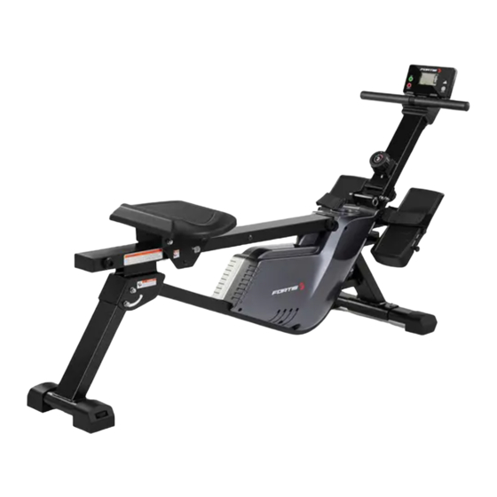
Summary of Contents for Kogan Fortis MR-300
- Page 1 MAGNETIC FLYWHEEL ROWING MACHINE (MR-300) FSMFWMR300A...
-
Page 3: Safety And Warnings
Always use the equipment as intended. If you find any defective components while assembling or checking the equipment, or if you hear any unusual noises coming from the equipment during exercise, cease use immediately and contact help.kogan.com for assistance. Do not use until resolved. - Page 4 • This equipment is designed and intended for indoor use only, not for commercial use. • This equipment contains no user-serviceable parts. If it suffers any failure or damage, cease use immediately and contact help.kogan.com.
- Page 5 OVERVIEW...
- Page 6 Part Description Part Description Main Frame Spacer on Shaft D10 Handlebar Ring D35 Braid Wheel Φ112 X 67.5 Seat Supporting Board R Spiral Spring T0.5 X 22 Seat Supporting Board L X 5080 PC Sheet Φ89.5 X Φ16 X Rear Support Frame Axle Φ22 X 130 Front Support Frame Magnetic Board...
- Page 7 Part Description Part Description Washer D8 X Φ16 X 1.5 Battery Cover Spring Φ1.5 X Φ16.7 X 49 X Battery Φ11.3 X N12 Tension Knob Φ1.5 X Magnet Location 45.5 X 130 X 10.5 700 X 42 Sleeve Φ8.2 X Φ12 X 12 Screw ST3 X 10 X Φ5.6 Bolt M8 X 100 X 15 X S6 Bolt M8 X 55 X 20 X S6...
- Page 8 ASSEMBLY Step 1: Adjust the Rear Support Frame (5) to a maximum angle as shown in the image below. Remove the pin (66). Open the front support frame (6) slowly in the direction shown in the image. Ensure not to clip two connecting wires in the tube. Fix the Front Support Frame (6) to the Main Frame (1) with knob (71) and washer (50).
- Page 9 Step 2: Attach the Front Stabiliser (8) to the Main Frame (1) using Bolt (90) and Washer (64). Tighten with a Spanner (A).
- Page 10 Step 3: Remove the Screws (22) from the back of Computer (14) with the Spanner(A). Connect the Computer Wire (14 a) with Inductor (15). Attach the Computer (14) to the Computer Pallet (17) using the Screw (22).
- Page 11 Step 4: Remove the Bolt (67), Washer (64) and Spring Washer (49) from the Seat (110) using the Spanner (A). Fix the Seat (110) to Seat Supporting Board L (4) and Seat Supporting Board R (3) with the Bolt (67), Washer (64) and Spring Washer (49).
- Page 12 Step 5: Attach the Pedal (24) to the Main Frame (1) using Bolt (23). Tighten with the Spanner (B).
- Page 13 Step 6: To use the Seat (110) for rowing exercise, pull out the Knob (72), rotate it clockwise 90 degrees then release it. The Seat (110) can now slide on the frame horizontally.
- Page 14 Step 7: Remove the Battery Cover (59) on the back of the computer (14). Insert two Batteries (60). Make sure the battery polarity (+/-) is correct while inserting the batteries. After the batteries are inserted firmly, replace the Battery Cover (59). Power on the Computer.
-
Page 15: Before First Use
BEFORE FIRST USE Tension Adjustment Increase Resistance: Rotate the Tension Knob (61) clockwise (in the B direction as shown in the image) to increase the level of resistance. The resistance is greatest when the Tension Knob is rotated to setting 8. Decrease Resistance: Rotate the Tension knob (61) counter-clockwise to decrease the level of resistance. - Page 16 Balance Adjustment: During use, if you notice that the machine is unbalanced, adjust the the height of End Cap (94). To adjust, rotate the End Cap (94) in A or B direction (as shown in the image) until the machine becomes level with the floor surface.
-
Page 17: Operation
OPERATION Functions MODE Press this button to change the display or to choose a program. In the setting mode, press this button to increase the setting value for TIME, COUNT and CAL. In setting mode, press this button to reset the value for TIME, COUNT and CAL. - Page 18 Folding the Machine Rotate the Knob (72) counter-clockwise to 90 degrees. Insert to the hole in the Main frame (1) to fix the Seat (110). Pull out the Pin (66) and loosen the Knob (71). Fold the Front Support Frame (6) as shown in the image.
- Page 19 Moving the Machine To move the machine, lift up the Rear Support Frame (5) until the Transportation Wheels on the End Cap (94) of Front Stabiliser (8) touch the ground. Once the Transportation Wheels are on the ground, you can transport the machine to the desired location.
- Page 20 Need more information? We hope that this user guide has given you the assistance needed for a simple set-up. For the most up-to-date guide for your product, as well as any additional assistance you may require, head online to help.kogan.com...
Need help?
Do you have a question about the Fortis MR-300 and is the answer not in the manual?
Questions and answers