Table of Contents
Advertisement
Available languages
Available languages
Quick Links
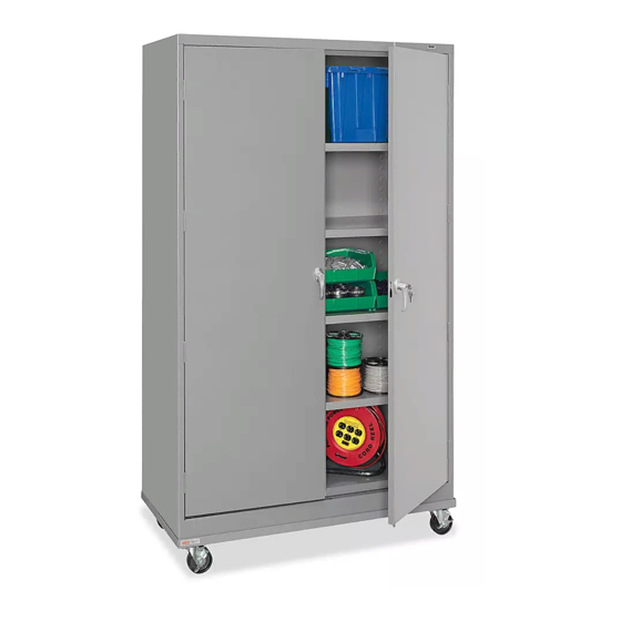
H-7811, H-8505
MOBILE STORAGE
CABINET
PAGE 1 OF 15
1-800-295-5510
uline.com
TOOLS NEEDED
Para Español, vea páginas 6-10.
Pour le français, consulter les pages 11-15.
11/32" Nut Driver
(included)
Flathead Screwdriver
Hammer
14 mm Wrench
CAUTION! Some parts may have sharp
edges. Take care when handling various
pieces to avoid injury. For safety,
wear work gloves when assembling.
0321 IH-7811
Advertisement
Table of Contents

Related Manuals for U-Line H-7811


Summary of Contents for U-Line H-7811
- Page 1 Para Español, vea páginas 6-10. Pour le français, consulter les pages 11-15. H-7811, H-8505 1-800-295-5510 uline.com MOBILE STORAGE CABINET TOOLS NEEDED 11/32" Nut Driver (included) Flathead Screwdriver Hammer 14 mm Wrench CAUTION! Some parts may have sharp edges. Take care when handling various pieces to avoid injury.
-
Page 2: Cabinet Parts
CABINET PARTS PRIMARY ASSEMBLY HANDLE ASSEMBLY DESCRIPTION QTY. DESCRIPTION QTY. Back Panel Locking Bar Set Left Side Locking Handle with Keys and Hardware Right Side Locking Cam Shelf Cotter Pin Sill Locking Bar Guide Insert (Nylon) Bottom Hinge Pin Nut Driver Left Door #8-32 x 3/8"... -
Page 3: Cabinet Assembly
CABINET ASSEMBLY NOTE: For assembled cabinet units, skip to 4. Attach the right side (3) to the back as done in step Mobile Base Assembly on page 5. 2. Make sure the flange is around the back and that the lances on the shelf adjustment strips are pointed Place the back (1) on a protected surface. - Page 4 CABINET ASSEMBLY CONTINUED Set the unit upright and tighten all nuts and bolts HANDLE/LOCKING SYSTEM INSTALLATION around the entire unit. 1. Place the locking handle (11) Figure 10 8. Insert the shelves (4) on the righthand door and Figure 7 at desired levels.
- Page 5 MOBILE BASE PARTS LIST Base x 1 Caster with Brake x 4 Bolt x 16 Lock Washer x 16 Nut x 16 MOBILE BASE ASSEMBLY 1. Align caster plate with bolt holes on base. Insert four 2. Tighten nuts with 14 mm wrench. bolts through base into caster plate.
-
Page 6: Herramientas Necesarias
H-7811, H-8505 800-295-5510 uline.mx GABINETE MÓVIL PARA ALMACENAMIENTO HERRAMIENTAS NECESARIAS Llave de Tuercas de 11/32" (incluida) Desarmador Plano Martillo Llave de 14 mm ¡PRECAUCIÓN! Algunas partes pueden tener bordes filosos. Debe tener cuidado cuando manipule varias piezas para evitar lesiones. Por seguridad, utilice guantes de trabajo cuando ensamble. - Page 7 PARTES DEL GABINETE ENSAMBLE PRINCIPAL ENSAMBLE DEL ASA DESCRIPCIÓN CANT. DESCRIPCIÓN CANT. Panel Posterior Juego de Barra de Bloqueo Lado Izquierdo Asa de Bloqueo con Llaves y Tornillería Lado Derecho Leva de Bloqueo Repisa Pasador de Chaveta Umbral Inserto para Guías de Barras de Bloqueo (Nylon) Parte Inferior Perno de la Bisagra Parte Superior...
- Page 8 ENSAMBLE DEL GABINETE NOTA: Para unidades de gabinetes ensamblados, 4. Fije el lateral derecho (3) a la parte posterior como lo pase a Ensamble de la Base Móvil en la página 10. hizo en el paso 2. Asegúrese de que el lateral rodee la parte posterior y que las lancetas en las tiras de Coloque la parte posterior (1) sobre una superficie ajuste de repisa apunten en la misma dirección que...
- Page 9 CONTINUACIÓN DEL ENSAMBLE DEL GABINETE Enderece la unidad y apriete todas las tuercas INSTALACIÓN DEL SISTEMA DE ASA/BLOQUEO y pernos que están en toda la unidad. 1. Coloque el asa de la puerta Diagrama 10 8. Inserte las repisas (4) en (11) en la puerta derecha Diagrama 7 los niveles que usted...
- Page 10 LISTA DE PARTES DE LA BASE MÓVIL 1 Base 4 Ruedas Giratorias con 16 Pernos 16 Rondanas de 16 Tuercas Freno Seguridad ENSAMBLE DE LA BASE MÓVIL 1. Alinee la placa de la rueda con los orificios de la 2. Apriete las tuercas con la llave de 14 mm. base.
-
Page 11: Outils Requis
H-7811, H-8505 1-800-295-5510 uline.ca ARMOIRE DE RANGEMENT MOBILE OUTILS REQUIS Tournevis à douille de 11/32 po (inclus) Tournevis à tête plate Marteau Clé de 14 mm MISE EN GARDE! Certaines pièces peuvent avoir des bords tranchants. Manipulez les pièces avec soin pour éviter toutes blessures. -
Page 12: Montage Initial
PIÈCES DE L'ARMOIRE MONTAGE INITIAL ASSEMBLAGE DE LA POIGNÉE DESCRIPTION QTÉ DESCRIPTION QTÉ Panneau arrière Barre de verrouillage (ensemble) Panneau latéral gauche Poignée de verrouillage avec clés et matériel d'installation Panneau latéral droit Came de verrouillage Tablette Goupille fendue Seuil de cadre Guide de barre de verrouillage (nylon) Tablette inférieure Axe de charnière... - Page 13 MONTAGE DE L'ARMOIRE REMARQUE : Pour les armoires montées, passez à la 4. Boulonnez le panneau latéral droit (3) au panneau section Montage de la base mobile à la page 15. arrière de la même manière qu'à l'étape 2. Assurez-vous que la bride est positionnée derrière le panneau arrière Placez le panneau arrière (1) sur une surface protégée.
- Page 14 MONTAGE DE L'ARMOIRE SUITE Placez l'unité à l'endroit, puis serrez tous les écrous INSTALLATION DE LA POIGNÉE/DU SYSTÈME DE VERROUILLAGE et boulons. 1. Placez la poignée de Figure 10 8. Installez les tablettes (4) verrouillage (11) sur la porte Figure 7 aux niveaux désirés.
- Page 15 LISTE DES PIÈCES DE LA BASE MOBILE Base x 1 Roulette avec frein x 4 Boulon x 16 Rondelle de blocage Écrou x 16 x 16 MONTAGE DE LA BASE MOBILE 1. Alignez la plaque de roulette avec les trous pour 2.
Need help?
Do you have a question about the H-7811 and is the answer not in the manual?
Questions and answers