Advertisement
Available languages
Available languages
Quick Links
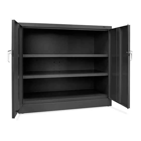
H-3619
COUNTER HIGH
STORAGE CABINET
PAGE 1 OF 15
1-800-295-5510
uline.com
Pour le français, consulter les pages 11-15.
TOOLS NEEDED
CAUTION! Some parts may have sharp
edges. Take care when handling various
pieces to avoid injury. For safety, wear
work gloves when assembling.
Para Español, vea páginas 6-10.
11/32" Nut Driver
(Included)
Flathead Screwdriver
Rubber Mallet
0321 IH-3619
Advertisement

Related Manuals for U-Line H-3619


Summary of Contents for U-Line H-3619
- Page 1 Para Español, vea páginas 6-10. Pour le français, consulter les pages 11-15. H-3619 1-800-295-5510 uline.com COUNTER HIGH STORAGE CABINET TOOLS NEEDED 11/32" Nut Driver (Included) Flathead Screwdriver Rubber Mallet CAUTION! Some parts may have sharp edges. Take care when handling various pieces to avoid injury.
- Page 2 PARTS PRIMARY ASSEMBLY HANDLE ASSEMBLY DESCRIPTION QTY. DESCRIPTION QTY. Back Panel Locking Handle with Keys (Set) Left Side Panel Locking Cam Right Side Panel Locking Bar (Set) Sill Lock Bar Guide Shelf Cotter Pin Left Door Dummy Handle Right Door Hinge Pin Bolts (32 x 3/8") Nuts (#8-32)
- Page 3 ASSEMBLY INSTRUCTIONS ASSEMBLING CABINET 3. Attach the top (8) to the unit by sliding the outer flange over the back of the unit and the side flange 1. Place the two back panels (1) on a protected surface. to the side panel. The threaded studs should go The flanges should be facing upward.
- Page 4 ASSEMBLY CONTINUED 5. Attach the sill (4) to the sides. Place nut loosely on 7. Set the unit upright and insert the other shelves, each of the studs and slide the ends of the sill into facing the edge with no slots toward the front of the the slots on both sides of the unit.
- Page 5 ASSEMBLY CONTINUED ATTACHING HANDLE 4. Hold the lock bars in position while sliding the lock bar guide (15) over the lock bar ends and through the door 1. Place the locking handle (12) on the right hand door slots. (See Figure 12) and fasten with two slotted bolts and lock washers.
- Page 6 H-3619 800-295-5510 uline.mx GABINETES DE ALMACENAMIENTO CON ALTURA DE MOSTRADOR HERRAMIENTAS NECESARIAS Llave de Tuercas de 11/32" (Incluida) Desarmador de Cabeza Plana Mazo de Hule ¡PRECAUCIÓN! Algunas partes pueden tener bordes filosos. Tenga cuidado al manejar las distintas piezas para evitar lesiones.
- Page 7 PARTES ENSAMBLE BASE ENSAMBLE DEL ASA DESCRIPCIÓN CANT. DESCRIPCIÓN CANT. Panel Posterior Asa de Bloqueo con Llaves (Juego) Panel Lateral Izquierdo Leva con Seguro Panel Lateral Derecho Barra de Seguridad Soporte Inferior (Juego) Repisa Guía de la Barra de Puerta Izquierda Seguridad Puerta Derecha Pasador...
- Page 8 INSTRUCCIONES DE ENSAMBLE ENSAMBLADO DEL GABINETE 3. Fije la cubierta (8) a la unidad deslizando el reborde exterior sobre la parte posterior de la unidad y el 1. Coloque los dos paneles posteriores (1) sobre una reborde lateral al panel lateral. Los pernos roscados superficie protegida.
- Page 9 CONTINUACIÓN DE ENSAMBLE 5. Fije el soporte inferior (4) a los lados. Coloque una 7. Ponga la unidad de pie y coloque las demás tuerca sin apretar en cada uno de los pernos y repisas, con la orilla sin ranuras hacia el frente del deslice los extremos del soporte en las ranuras gabinete.
- Page 10 CONTINUACIÓN DE ENSAMBLE INSTALAR EL ASA 4. Sostenga las barras de seguridad en posición mientras desliza la guía de la barra de seguridad (15) 1. Coloque el asa de bloqueo (12) en la puerta en el extremo de la barra de seguridad y a través derecha y asegure con dos pernos ranurados y de las ranuras de la puerta.
- Page 11 H-3619 1-800-295-5510 uline.ca CABINET D'ENTREPOSAGE HAUTEUR COMPTOIR OUTILS REQUIS Tournevis à douille de 11/32 po (compris) Tournevis à tête plate Maillet en caoutchouc MISE EN GARDE! Certaines pièces peuvent avoir des bords tranchants. Faites attention lorsque vous manipulez les diverses pièces, afin d'éviter les blessures.
- Page 12 PIÈCES ENSEMBLE PRINCIPAL ENSEMBLE DE LA POIGNÉE DESCRIPTION QTÉ DESCRIPTION QTÉ Panneau arrière Poignée de verrouillage avec clés (ensemble) Panneau latéral gauche Came de verrouillage Panneau latéral droit Barre de verrouillage Seuil de cadre (ensemble) Tablette Guide de barre de Porte de gauche verrouillage Porte de droite...
- Page 13 INSTRUCTIONS DE MONTAGE MONTAGE DE L'ARMOIRE 3. Fixez le dessus de l'armoire (8) à l'unité en glissant la bride extérieure par-dessus l'arrière de l'unité et 1. Placez deux panneaux arrière (1) sur une surface la bride latérale par-dessus le panneau latéral. Les protegée.
- Page 14 MONTAGE SUITE 5. Fixez le seuil de cadre (4) aux côtés. Placez les 7. Positionnez l'unité à la verticale et insérez les autres écrous lâchement sur chacun des goujons et glissez tablette avec le rebord sans fentes orienté vers les extrémités du seuil de cadre dans les fentes sur l'avant de l'armoire.
- Page 15 MONTAGE SUITE FIXATION DE LA POIGNÉE 4. Maintenez les barres de verrouillage en position tout en faisant glisser les guides de barre de verrouillage (15) 1. Placez la poignée de verrouillage (12) sur la porte sur les extremités des barres de verrouillage et à de droite et fixez à...
Need help?
Do you have a question about the H-3619 and is the answer not in the manual?
Questions and answers