Table of Contents
Advertisement
Quick Links
Advertisement
Table of Contents

Subscribe to Our Youtube Channel
Related Manuals for Apex Digital 2037M-D


Summary of Contents for Apex Digital 2037M-D
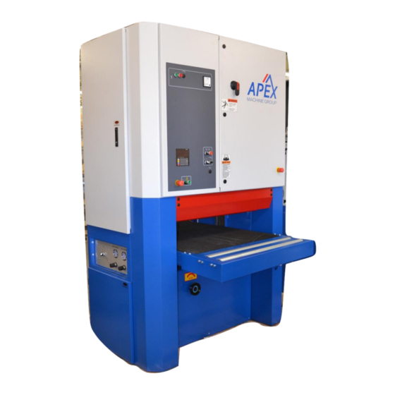
- Page 1 Operation Manual Model 2037M-D Serial No 180413...
-
Page 2: Warranty And Service
Warranty and Service APEX Machine Group warrants every product it sells. If you need service or repair, contact us or one of our Service Dealers WARRANTY Apex Machine Group machines carry a limited warranty which varies in duration based upon the product. WHAT IS COVERED? This warranty covers any defects in workmanship or materials subject to the exceptions stated below. - Page 3 Machine Warranty Registration By e-mail at : www.apexmachinegroup.com Or mail a registration card to : Apex Machine Group 4700 Olson Memorial Highway Golden Valley, Minnesota 55422 Warranty Registration Card Model No. __2037M-D____________________________ Serial No. ___180413___________________________ Date Purchased : _________________________ Company Name : _________________________ Address : _____________________________ _____________________________...
-
Page 4: Table Of Contents
Table of Contents Warranty and Service ................1/2 Table of Contents ................... 3 Parts List ……………………………………………………………………. 4 Warning....................5/6 Introduction .................... 7 Specifications ..................7 Unpacking ....................8 Contents of the Shipping Container ............8 Assembly ....................9 Air Supply Connection................9 Installing/Replacing Sanding Belt ............10 Grounding Instructions ................ -
Page 5: Parts List
Parts List BOM List 180413……………………………………........Dimensional Drawing 7390020067…………….……………..... 33 Main Frame Assembly 7390041035…………………....... Upper Frame Sub Assembly 7390042033…..……........Cover Assembly 7390019048..………………………......... 36 Contact Drum Assembly 7390010021..……..………………...... 37 Contact Drum Frame Assembly 7390048013.…..………………....38 Drum Idler Roll Assembly 7390055006 …………………………………….. 39 Drum Head Limit Switch Assembly 7390049005 ………………………….. -
Page 6: Warning
Warnings Please note: You can be badly injured working on or around a Sander. Only do service work for which you have the knowledge and proper equipment. If you have any doubt about your ability to perform a service job, please call our tool free line at 877-754-7266 or 855-500-7239 or contact an authorized dealer to schedule a qualified technician. - Page 7 15. Check damaged parts. Before further use of the machine, a guard or other part that is damaged should be carefully checked to determine that it will operate properly and perform its intended function. Check for alignment of moving parts, binding of moving parts, breakage of parts, mounting and any other conditions that may affect its operation.
-
Page 8: Introduction
APEX Machine Group who can also be reached at our web site: www.apexmachinegroup.com 855-500-7263. Specifications Model Number................2037M-D Working Width (in.) ..................36” Maximum Thickness (in.)................5 ½” Minimum Part Length (in.)................16” Table Height from Floor (in.) ..............41”... -
Page 9: Unpacking
Unpacking Open shipping container and check for shipping damage. Report any damage immediately to your distributor and shipping agent. Do not discard any shipping material until the sander is installed and running properly. Compare the contents of your container with the packing list to make sure all parts are intact. Missing parts, if any, should be reported to your distributor. -
Page 10: Assembly
Assembly The sander should be placed on a level, sturdy floor, preferably concrete, with plenty of space surrounding it for on- and off-loading of stock, and general maintenance work. Open the two lower panels infeed and outfeed, leveling screws inside the cabinet (Figure 1) to level the sander. -
Page 11: Installing/Replacing Sanding Belt
Installing or Replacing Sanding Belt 1. Machine should be disconnected from power source. 2. Turn the air valve switch (A, Figure 3) to Off position. 3. Remove the lock screw (B, Figure 3) by turning it counterclockwise and lifting up. 4. -
Page 12: Grounding Instructions
Grounding Instructions Electrical connections must be made by a qualified electrician in compliance with all relevant codes. This machine must be properly grounded while in use to help protect the operator from electrical shock and possible fatal injury. In the event of a malfunction or breakdown, grounding provides a path of least resistance for electric current to reduce the risk of electric shock to the operator. -
Page 13: Operation
Operation 1. Make sure the machine is always disconnected from the main power supply. Place a warning placard (if used) on the fuse holder or circuit breaker to prevent it being turned on while the machine is being wired. Always follow proper Lock Out/Tag Out procedures when performing any wiring on this machine. -
Page 14: Adjustments
Adjustments Sanding Belt Tracking and Oscillation The sanding belt should oscillate left and right without a tendency to slide off the rollers. If the sanding belt runs outside of the normal track, it will contact a limit switch and the machine will stop automatically. -
Page 15: Sanding Belt Tracking And Oscillation
Sanding Belt Oscillation Belt oscillation is done with a photo electric tracking eye and a air solenoid valve. When the sanding belt is operating the edge of the belt will pass across the light beam , which will then activate a solenoid valve that will allow air to pass to the tracking cylinder and pivot the upper idler roll. -
Page 16: Contact Drum Adjustment Metal Machine
Adjusting Contact Drum for Abrasive Belt Thickness If using sanding belts that vary a lot in thickness ( Example : 220 cloth back to a 80 grit belt ) Follow the procedure below to “ raise or lower “ contact drum depending on abrasive belts you are using . -
Page 17: V-Belt Tension And Replacement
V-Belt Tension and Replacement For the first few days of operation new belts should be checked occasionally and adjusted for tension as necessary until the belts are properly “worn in.” The v-belts on the main motor should be checked for proper tension. Tighten any of the v-belts as follows: 1. -
Page 18: Conveyor Belt Tension
Conveyor Belt Tension Check the tension of the conveyor belt on the infeed and outfeed rollers – the conveyor belt should be tight enough that you cannot shift it with your hands. If the conveyor belt needs tightening, proceed as follows. 1. - Page 19 Keep hands away from the moving conveyor belt. 1. Turn on the conveyor belt. 2. Adjust tracking using the same adjustment screws that were used for tensioning in Figure 10. 3. If conveyor belt is moving to the right side, turn the right screw clockwise.
-
Page 20: Feed Rate
Feed Rate The feed rate is infinitely variable within the provided range, in order to meet the sanding requirements of a wide variety of materials. Selecting a proper feed rate is largely a matter of experience. In general, soft woods require a higher feed rate, while hard woods require a lower feed rate. - Page 21 4. Raise the table manually using the handwheel (Figure 13) until the panel or set up block contacts the pressure roller. 5. Make sure the pressure at the right and left side of pressure roller is even. 6. If adjustment is needed, release the lock nut ( Figure 14 ) with a 14mm wrench.
- Page 22 Table Parallelism Parallelism of the conveyor table to the contact roller has been factory-set and should not require further adjustment. However, as the machine receives extended use, this setting should be checked. First look at contact drum for wear and then inspect parallelism by one of two methods.
-
Page 23: Operating Controls
Operating Controls Figure 17 shows the control panel functions. 1. The emergency stop button shuts down all machine operations. The button remains engaged after being pushed. To disengage, rotate the ring until the emergency stop button pops back out. The emergency stop cover has a plate (shown in Figure 16 ) which shuts down all machine operations when it is pushed. -
Page 24: Operation
Operation Before operating the sander, make sure that: 1. The dust collection system or water is turned on. 2. Sanding belt tracking and oscillation are working properly. 3. Conveyor belt tracking is correct. 4. All screws and handles are tightened securely. -
Page 25: Maintenance
Maintenance Before doing any maintenance on the sander, disconnect it from the electrical supply by pulling out the plug or switching off the main switch. Failure to comply may cause serious injury. The interior of the machine should be thoroughly cleaned each day after using the sander. -
Page 26: Troubleshooting The Sander
Troubleshooting the Sander Trouble Probable Cause Remedy Sander will not start. No incoming power. Check that sander is connected to power, fuses are not blown or circuit breakers are not tripped. Low voltage. Check voltage at power source. Loose wiring. Inspect and remedy any loose connections on sander. - Page 27 Trouble Probable Cause Remedy Uneven thickness between the Table not positioned correctly in Adjust table until it is parallel left left and right sides of the relation to contact drum. to right (pages 17-18). workpiece. Front hold down roller not in Adjust front hold down roller so correct position in relation to parallel.
-
Page 28: Replacement Parts
Replacement Parts Replacement parts are listed on the following pages, use these pages to find the parts you need to order and follow the instructions listed below. How To Order Parts APEX Machine Group 4700 Olson Memorial Highway Golden Valley , Minnesota 55442 Toll-Free: (855) 500-7263 Local: (952) 224-2899 www.apexmachinegroup.com... -
Page 29: Recommended Spare Parts
Replacement Parts List These are parts we recommend you purchase. These are replacement parts that will normally be needed during the service life of your machine. By having these on hand your machine down time will be minimized. Description 4....Pinch Roll Bearings 4....Pinch Roll Springs 2....Bearings, Flange Contact drum 2………..Bearing brush roller... - Page 30 Apex Machine Maintenance Continual, scheduled maintenance by trained personnel is advised to keep the Apex machine functioning as safely and effectively as possible. To avoid unnecessary wear and the potential breakdown of the machine, the following scheduled maintenance procedures should be performed on the machine regularly. The maintenance of the Apex sanders is based on the sander running a full 8 hour shift per day.
- Page 31 Machine number 2037M-D Serial# 180413 Scheduled maintenance performed by Date Scheduled maintenance performed by Date Scheduled maintenance performed by Date Scheduled maintenance performed by Date Scheduled maintenance performed by Date Scheduled maintenance performed by Date Scheduled maintenance performed by Date...
- Page 32 M 15 Set – UP For Programming Thickness T enter the thickness of the material to be obtained with the M15 unit ,the following steps should be followed: 1. Press the yellow button on the keypad labeled "Prog" 2. Enter the thickness you desire by pressing the buttons on the keypad. Such as: .125 for 1/8".
- Page 33 2037M -D -0007 180413 ITEM N umber Description DIMENSIONAL GCP-7390020067 GCP-7390041035 MAIN ASSY,UPPER FRAME GCP-7390042033 UPPER FRAME SUB-ASSY 2-1-1 GCP-7390032009 ELECTRICAL ENCLOSURE GCP-7390034009 TRIP BAR ASSY,OVERTHICK GCP-7390097001 CLEANING BRUSH ASSY GCP-7390019048 COVER ASSEMBLY GCP-7390033004 SWITCH ASSY,DOOR GCP-7390006046 CONVEYOR ASSY GCP-7390007018 DRIVE ASSEMBLY,CONV 5-1-1 GCP-7390029017...
- Page 60 2037M-D(180413) 230/3/60 ELECTRICAL PARTS LIST 2018-11-28 DESCRIPTION SYMBOL ELECTRICAL DIAGRAM 160227-E1~E2 CONTROL POWER (FLA 0.65A) CONTROL RELAY, OMRON LY2NJ-AC120 CR-M CONTROL RELAY SOCKET, OMRON PTF08A-E CR-M CONTROL RELAY, OMRON LY2NJ-AC120 CR-22A CONTROL RELAY SOCKET, OMRON PTF08A-E CR-22A DISCONNECT SWITCH ABB OT100F3...
- Page 61 HEAD NO. 1 (FLA 54.0A) 20HP,1800,230/3/60 MTR-1 SCHNEIDER GV3P65(48-65A) MCC-1 SCHNEIDER GVAE11 (1NO/1NC)) MCC-1 SCHNEIDER LC1D32F7 110V (1NO/1NC) M-1M SCHNEIDER LC1D32F7 110V (1NO/1NC) M-1R,S SCHNEIDER LAD9R1 M-1R,S SCHNEIDER LAD9P3 M-1S SCHNEIDER LADS2 TR-1 TAHSING SR-72 100:5 / TAHSING CURRENT COIL100:5 AM/CT-1 CONTROL RELAY, OMRON LY2NJ-AC120 CR-1A...
- Page 62 SCHNEIDER LC1D09F7 110V (1NO/1NC) MF-7 SCHNEIDER LC1D09F7 110V (1NO/1NC) MR-7 SCHNEIDER LAD9R1 MF-7,MR-7 TEND TZ-7311 LS-7A,B MOELLER M22-WK3/K20 SS-7 SUPPRESSOR POWERMATION 1uF 120OHM2E 1G20 RC-7A,7B OPENING CONTROL/FEED SPEED INDICATION MINIKOL M15S WITH AC TECH STYLE VFD MODBUS/CABLE HMI-7 POWER SUPPLY COTEK DN-20-24 PWS-7 SCHNEIDER C60N 1P C1A-24425-UL1077 CB-24...
- Page 63 230/3/60 2037M-D(180413) VFD PARAMETER TABLES 2018-11-28 PARAM SETTING PARAMETER DESCRIPTION PASSWORD P199 RESET TO 60HZ DEFAULTS SETTINGS P100 START/STOP FROM TERMINAL STRIP P101 0-10VDC SPEED REFERENCE P103 FEED VFD MAX FREQ P104 VFD-6 ACCEL TIME P105 AC TECH DECEL TIME...
- Page 64 230/3/60 2037M-D(180413) MINIKOL PARAMETER TABLES 2018-11-28 PARAM SETTING PARAMETER DESCRIPTION - DIR OR (DIR-) COUNTING DIRECTION |----- POSITIONING MODE 0.000 INCH SOFTWARE LIMIT LOW 5.000 INCH SOFTWARE LIMIT HIGH DELTA, TE, AC TECH, AC M15S F16 AC TECH 1000 0.001 INCH...
- Page 65 ENTER VOLTAGE ENTER LARGEST MOTOR CALCULATION RESULTS 101.4 Time delay fuse 141.9 Inverse time breaker Apex Machine Group Minneapolis, Minnesota USA 180413 Serial 2037M-D Model: Voltage: Amps MTR-1: FLA: Amps VFD-6: FLA: Amps MTR-7: 0.25 FLA: 1.25 Amps T-21: FLA: 0.65...
- Page 67 2037M-D(180413) 230/3/60 PNEUMATIC PARTS LIST 2018-11-28 DESCRIPTION SYMBOL PNEUMATIC SCHEMATIC 160227-P MAIN AIR AIR FILTER/REG PARKER P31EA12EGBBNNP- P31KA00MW AF-1 PRESSURE GAUGE SM P/N D1-0040-5, 2" , 150 PSI, 1/4" NPT PG-1A,B PRESSURE REG SM P/N D1-0043-2, KAO-LU CT-20R, 7-128 PSI PR-1A,B HEAD NO.1...
Need help?
Do you have a question about the 2037M-D and is the answer not in the manual?
Questions and answers