Table of Contents
Advertisement
Advertisement
Table of Contents

Related Manuals for Thor Kitchen HC-767


Summary of Contents for Thor Kitchen HC-767
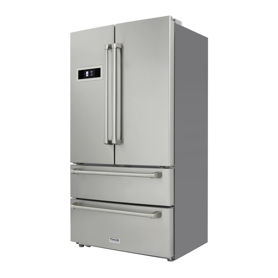
- Page 1 Repair Manual HC-767...
-
Page 2: Table Of Contents
Contents 1. Warnings and precautions for safety ................. 3 2. External Views ........................4 2.1 External Size ........................ 4 2.2 Description of Parts ....................5 2.3 Cold air circulation ....................... 6 3. Specification ........................7 4. Operation and functions ....................9 4.1 Display ......................... - Page 3 7-6 Disassembling Condenser Fan ................. 40 8. Trouble Diagnosis......................41 8.1 Faulty Start (R/F compartment Lights Off, Front PCB Power OFF)......41 8.2 Freezer Compartment Failure ................... 42 8.3 Refrigerator failure ..................... 48 8.4 Operation Noise of Refrigerator ................54 8.5 Door Failure .......................
-
Page 4: Warnings And Precautions For Safety
1. Warnings and precautions for safety Please observe the following safety precautions in order to use safely and correctly the refrigerator and to prevent accident and danger during repair. Unplug the power cord from wall outlet and wait at least three minutes before replacing PCB parts. -
Page 5: External Views
2. External Views 2.1 External Size Measurements in mm(inches) - Page 6 2.2 Location of Parts Name Door switch Butter case R-compartment glass shelf Door bin Fruit and vegetable cases F-compartment drawer components Small door shelf Folded glass shelf F-compartment upper drawer Ice maker components F-compartment lower drawer...
-
Page 7: Cold Air Circulation
2.3 Cold air circulation... - Page 8 911x782.5x1775mm(with handle) 35.9”x28.7” x69.9”(inches) 35.9”x30.8” x69.9”(inches) 1.8(Outer diameter)x0.7 (Wall thickness)xL3000(Length)(mm) 0.071”(Outer diameter)x0.0276” (Wall thickness)xL118”(Length)(inches) 1.8(Outer diameter)x0.7 (Wall thickness)xL3000(Length)(mm) 0.071”(Outer diameter)x0.0276” (Wall thickness)xL118”(Length)(inches)
-
Page 9: Specification
Item Specification Model name Sheath R AS 115VAC, 120W Sheath F AS 115VAC, 250W Reversal beam heating wire 115VAC, 11W Heater Heating wire of air duct in 12VDC, 0.5W refrigerator bottom drawer Water inlet pipe heating wire of 12VDC, 2.5W ice maker Power cord 125VAC, 15A (UL) + Label... -
Page 10: Operation And Functions
4. Operation and functions 4.1 Display Panel Input Control object Front PCB button Temp. set of Refrigerator/Freezer Eco Mode, Auto mode Ice-make ON/OFF Alarm, lock/unlock Ice-maker ON/OFF Lock/Unlock Energy saving Auto mode Temperature adjustment button Temperature adjustment button for freezing compartment for refrigerator compartment Display control Control mode... - Page 11 8℃ 7℃ 6℃ 2℃ 46℉ 45℉ 44℉ 36℉ 4) Hold down refrigerator temp. Button 3s to on or off super cool, refrigerator temp. Zone display Trs= 2℃(36℉),be active after lock. 3.“Freezer Temp”Button 1)Temperature control of freezer compartment 2)Temperature can be set cyclically 3)Each press change 1℃/1°F -13℃...
- Page 12 maker starts working, effective after 15s. when the freezer set the temperature into -13~-18℃,choose ice make mode, the temperature of display changed into -18℃. When the “Ice Make on/off” is pressed and the “Ice Make” icon lights off, the ice maker stops working, effective after locked.
- Page 13 ※ TICE explanation: Water supply → ice making → ice dropping → reset 2.Exceptional operation 1) When the consumer input stops in off-ice and water supply If the "off" and "ice" is just in operation when the ice-making mode is cancelled in "off" and "ice"...
-
Page 14: Auto Defrost Mode
4-3. Auto defrost mode 1. Defrosting cycle 1. Comp 2. F/R/C-Fan 3. FD/RD Heater CONTENTS REMA 1. Defrost Mode Heater Heater Defrosting Defrosting 1) Comp, F/R-Fan: OFF FD/RD Heater: ON 2) Time limit 30 Sec.: Heater is ON regardless of D-sensor temperature right after defrosting start. - Page 15 2) Defrosting mode starts unconditionally as long as total comp. work time is 4 hours at the first time, even if the above conditions 1) are not satisfied. 3) Even if conditions 1) and 2) are not met, the defrosting cycle varies along with the open temperature and ambient temperature.
- Page 16 Comments Remark Flow chart of defrosting start: 1、Select the defrost cycle time according to the table below Ambient temperature Constant High Superhigh temperature temperature temperature temperature ( X<21℃ ) (21℃≤X<28℃) (28℃≤X<35℃) (35℃≤X) None (open the door, thermostat, special mode and fault) Door open Overload Others...
- Page 17 In “unlock” mode, push “Fridge temp.” button 3 seconds while pushing “Freezer temp.” button simultaneously, when entering, there is a beep sound, click the “FRZ.TEMP .” button 3 times continuously, until it shows 3.
-
Page 18: Fan Voltage Of Control Mode
4.5 Fan voltage of control mode INPUT CONTROL OBJECT 1. F-Sensor 1. F FAN, R FAN, C FAN 2. R-Sensor CONTENTS REMARKS 1. Fan voltage of control mode Freezer Refrigerator Condenser Voltage 9.1v 10.1 v 10 V 4.6 Water PIPE Heater Control INPUT CONTROL OBJECT 1. -
Page 19: Error Display
R-lights turn off when R-door closed. Lights turned off when refrigerator compartment closed. 2 Control of Freezer Compartment Lights R-lights turn ON/OFF by R-door switch ON/OFF; over 1.5minutes after the door opened, the lights turn off automatically. Lights turned off when Freezer compartment closed. 4.9 Error Display INPUT CONTROL OBJECT... - Page 20 T<-50℃(-58℉) T>50℃(122℉) T<-50℃(-58℉) T>50℃(122℉) T<-50℃(-58℉) T>50℃(122℉) 3 seconds 3 seconds 3 seconds 3 seconds to close...
-
Page 21: Super Cool Of Freezer Or Refrigerator
4-11: Super Cool of Freezer or Refrigerator INPUT CONTROL OBJECT Front PCB button The temperature range of Freezer & Freezer Set, Refrigerator Set Refrigerator is specified. Super Refrigerate, Super Freeze CONTENTS REMARKS 1. How to start 1 “Freezer compartment”: Under “unlock” mode, press “Freezer Temp.” 3 seconds, runs to Super Freeze. -
Page 22: Wiring Diagram
5. Wiring Diagram... -
Page 23: Component Locate View
6. Component Locate View 6.1 Refrigerator Compartment Guide seat R-compartment air duct Dome lamp R DR *R switch R DR *l switch Shelf Side lamp Fruit and vegetable cover plate Bottle holder Chill compartment cover Front display panel... -
Page 24: Freezer Compartment
6.2 Freezer Compartment Ice maker Ice storage case Freezer upper drawer Drawer splitter plate Drawer clapboard Freezer lower drawer Freezer fan Freezer evaporator heating tube plug Freezer duct Freezer fan plug Freezer light Freezer Freezer evaporator evaporator heating tube... -
Page 25: Automatic Ice Maker Compartment
6.3 Automatic Ice Maker Compartment Components of ice-maker Ice storage case Ice-maker motor Ice maker support Ice cube Knob Ice probe rods Air outletof Ice cube... -
Page 26: Machine Compartment
6.4 Machine Compartment Condenser Fan Dryer Condenser Compressor Water valve Drain Solenoid Compressor Water tray Power cord valve installation plate 7. How to Check Each Parts 7.1 Ice Maker Assembly NO DISASSEMBLING PROCEDURE NO DISASSEMBLING PROCEDURE Disassemble the motor terminal of ice maker Remove the knob and ice cube components... - Page 27 Disassemble the motor of ice maker The ice cube support is fixed on 1 . Grasp firmly this part and pull out. the refrigerator by 4 hangers, pull out 2 . Then take out joint terminals, the ice the ice cube support. maker can be dismantled.
-
Page 28: Dispenser Solenoid Valve
7.2 Dispenser Solenoid Valve 1) Disassembling Procedure NO DISASSEMBLING PROCEDURE NO DISASSEMBLING PROCEDURE Remove rear cover Disassemble the valve and pipe connection terminals Remove the water valve of the ice maker Remove the outer water connector 2) How to check water valve PARTS SPEC. -
Page 29: Main Pcb
7-3. Main PCB Model: FRS-702ETU Relay power * To check normal voltage of each electrical controller devices to & from MICOM Check input & output voltage of MICOM and IC12. Fan Power * To check input & output voltage Controller of Fan #1: Input #2: Output... - Page 30 Regulator IC *To check voltage of MICOM and IC6. (5V) Voltage check of IC6 (#1: input:12V; #2: output: Control of Ice * To check voltage of MICOM and IC10, and the Maker output voltage of IC10 Check the IC10 voltage (#4,5,6:Input+5V #10, 2, 3: Output: 12V) Fig.-1 Use an...
- Page 37 Check if voltage output or not Fig.-3 UVW-Anticlockwise Fig.-3 Compressor terminal Fig.-4...
-
Page 38: Pcb Display Panel
Correspond rated power of different ambient temperature Ambient Below 22 (71.6°F) 28℃ 35℃ Over 35℃(95°F) (71.6~82.4°F) (82.4~95°F) temperature range Change range 105W 95 130W 125 160W 140 190W of rated power REMARKS: 10W deviation should be considered normal when actual power compare with the above rated power. -
Page 39: Disassembling Condenser Fan
Pull the upper part of the L-shaped level Unplug the terminal Pull up, unplug the slot 7-6 Disassembling Condenser Fan NO DISASSEMBLING PROCEDURE NO DISASSEMBLING PROCEDURE Remove the condenser fan base Remove the rear cover Unplug the connector of the condenser Remove the condenser fan Use a screwdriver to pry the bottom, and pull out... -
Page 40: Trouble Diagnosis
8. Trouble Diagnosis 8.1 Faulty Start (R/F compartment Lights Off, Front PCB Power OFF) Whether there is light or sound of Check the fault location the display panel? according to the error code See Schedule 1 Check display panel is R-compartment lights plugged normal or not? up or not? -
Page 41: Freezer Compartment Failure
8.2 Freezer Compartment Failure Removing and replacing Freezer parts Disassembling F Door procedure Remove foods Remove F Drawer Case & F Case in freezer compartment Remove the upper Freezer drawer Push the lock on the metal rail Remove the upper F Door Assembling of rail connecting rod and gear... - Page 42 Remove the lower F drawer, as well as the lower F door Remove the ice maker components 3) Disassembling F Louver AS procedure * Remove 4 screws on the duct cover * Pry the lock with a flathead screwdriver * Pull forward to remove the duct cover, *Duct cover disassemble the fan terminal 4) Freezer room fan disassembly...
- Page 43 * Pry the two fixture locks of the motor with a * Remove the motor fixture locks flathead screwdriver * Remove the locks of evaporator aluminum plate with a flathead screwdriver, top and down side has 4 locks respectively. * Use a Phillips screwdriver remove three screws fixing on the fan motor Change of F Lights Change of F Door Switch * Pry the switch...
- Page 44 2) Freezer failure Start Any error code of Check error code tips Compressor works Check compressor/OLP is ok Replace compressor F-fan/C-fan is ok or Replace fan motor F-fan/C-fan works ok? not? Wiring connection is Replace Main PCB ok or not? Check the wirings F-Sensor is ok Replace sensor...
- Page 45 3) Freezer ice formation or frost problems Start Dews are formed on the Check door is Close the door gasket inside closed or not? F-compartment Explain not to open doors too Door is open and frequently closed too frequently? Make enough distance between Whether have heat appliances near the the appliances and refrigerator...
- Page 46 4) Freezer LED light maintenance Start Power of F-Lamp is Check the power connection and ok? (DC12V) terminal plug LED lamp is damaged or not? F-compartment lamp Replace the LED lamp switch is normal or not? Lamp switch is connected Repair the F-door switch correctly or not? Completed...
- Page 48 *Remove the wire connector * R-compartment air duct cover Removing and replacing Refrigerator parts 2) Disassembling Multi-Duct procedure *Remove 2 phillips head screws *Remove 6 points with flathead screwdriver * Unscrew 3 Phillips head screws of the fan, remove the aluminum evaporator plate, and disassemble the variable temperature duct foam and the electric throttle Change of R Door Switch Change of R Lights...
- Page 49 *Disassembly procedure of the right hinge cover and light switch is the same as the left...
- Page 50 2) Refrigerator compartment Troubleshooting Start Any error code on Front PCB? Solve the error codes Have fan motor Does R-compartment Replace the motor or not? fan work normal? Are wires and terminals Replace the main PCB normal or not? Check the wiring R-Sensor works Check the sensor terminal and normal?
- Page 51 3) Refrigerator compartment LED lamp checking Start Power of R-Lamp Check the power connection is ok? (DC12V) LED lamp is Replace LED lamp damaged? Connection of R Repair the R-door switch door switch is ok? Check the R-door switch connection...
- Page 52 4) Check for moisture and ice formation of R-compartment Start If R room door end cap and Check the gasket have condensation Close the door door close or or not. not? Door is open and Advise users don not to open closed too doors frequently frequently?
-
Page 53: Operation Noise Of Refrigerator
8.4 Operation Noise of Refrigerator 1) Compressor Operation Noise Start Level the refrigerator by adjusting If refrigerator is placed in level? wheels Back cover of compressor is Install in place assembled right? Compressor damping Replace the damping rubber rubber is deformed, aging? Attach a restrainer on the comp. - Page 54 2) Refrigerant Flow Sound Start Attach an damping rubber on Water flowing or hiss sounds from the the capillary tube. refrigerator? Sound of Hiss or Apply an damping rubber on the sizzling when comp. accumulator starts? Sound of Hiss or Apply an damping rubber on the sizzling when accumulator...
- Page 55 3) Fan Noise Start Fan is damaged or Replace the fan transformed Fan is touching the Adjust it as necessary surround? Fan-motor assembly is Adjust it as necessary moving or shaking? Motor has its own noise or vibration Replace the motor assembly when working? Explain to the customers how fan is working to circulate cold air in the compartments.
- Page 56 4) Pipe Noise Start Pipes are touching Separate the touching pipes, if any in the machine compartment? Do the compressor and Replace the Comp. base, apply condenser fin have vibration or abnormal noise? buffer material to condenser. Apply damping rubbers on the Pipe itself is shaking much? pipes to reduce the shaking.
-
Page 57: Door Failure
8.5 Door Failure Start Check if F &R Lamp is ON. Door switch activated? Attach a thin pad on the door liner or change the door assembly. Door switch is soaked with water or there is water in the switch? Change the door switch PCB input is ok? Repair any disconnection of wires... -
Page 58: Cooling Cycle Heavy Repair
9. Cooling Cycle Heavy Repair ! WARNING: Only a qualified refrigeration technician could attempt a sealed cooling system repair. 9.1 Summary of Heavy Repair Process Contents Tools Cut off pipe ends(compressor, dryer), discharge Clean refrigeration Nipper, side cutters the refrigeration liquid from dryer and compressor. residuals 1. -
Page 59: Precautions During Heavy Repair
9.2 Precautions During Heavy Repair Items Precautions Use of tools Use special parts and tools for R134a,R600a 1. Remove retained refrigerant more th an 5 m inutes after turning off a refrigerator. (if not, oil will leak inside) 2. Remove retained refrigerant by cutting first high pressure side (dryer Removal of part) w ith a nipper a nd the n cut low pressure s ide.(if the order is n ot retained refrigerant... -
Page 60: Practical Work For Heavy Repair
9.3. Practical Work for Heavy Repair Items Precautions 1. rem oval of res idual 1 remove residual refrigerant more than 5 minutes later after turning off the refrigerator. (If refrigerant not, compressor oil may leak inside.) 2 remove retained refrigerant slowly by cutting first high pressure side (dryer part) with a nipper and then cut low pressure side. - Page 61 Items Precautions 3.Vacuum degassing * Pipe connection Connect a red hose to the high pressure side and a blue hose to the low pressure side. * Vacuum sequence Open valves and evacuate for 40minutes. Close valve . KEY POINTS 1) If power is applied during vacuum degassing, vacuum degassing shall be more effective. 2) Operate compressor while charging refrigerant.
-
Page 62: Standard Regulations For Heavy Repair
Items Precautions 4.Refrigerant charging 4) Refrigerant Charging Charge refrigerant while operating a compressor as shown above. 5) Pinch a charging pipe with a pinch-off plier after completion of charging 6) Braze the end of a pinched charging pipe with copper brazer and take a gas leakage test on the welded parts. -
Page 63: Brazing Reference Drawings
9.5 Brazing Reference Drawings. Brief introduction of refrigeration system of French door refrigerator Condensation... -
Page 64: Ice Maker
10. Ice Maker 10.1 Dispenser Water Flow Connector F-Compartment Inlet pipe Inlet pipe Ice maker Water valve Outlet pipe...
Need help?
Do you have a question about the HC-767 and is the answer not in the manual?
Questions and answers