Table of Contents
Advertisement
Advertisement
Table of Contents

Related Manuals for Thor Kitchen HRF3603F


Summary of Contents for Thor Kitchen HRF3603F
- Page 1 Refrigerator Service Manual Model:HRF3603F...
-
Page 2: Table Of Contents
Contents 1.Warnings and precautions for safety ........2 2.Appearance and structure 2.1 View of the appliance .............3 2.2 Wind channel structure ............4 2.3 Evaporator structure ..............6 ............7 2.4 Compressor room structure 3.Basic parameters ..............8 4.Operation and functions 4.1 Display controls ..............9 4.2 Defrost mode ...............12 4.3 Compulsory defrost mode... -
Page 3: Warnings And Precautions For Safety
1.Warning and precautions for safety 1 Warning and precautions for safety Please observe the following safety precautions in order to use safely and correctly the refrigerator and to prevent accident and danger during repair. 1. Be care of an electric shock. Disconnect power cord from wall outlet and wait for more than three minutes before replacing PCB parts.Shut off the power whenever replacing and repairing electric components. -
Page 4: Appearance And Structure
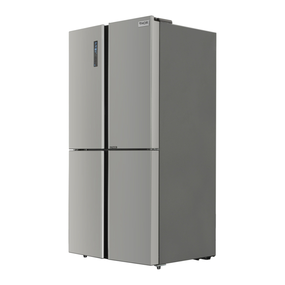
2.Appearance and structure 2 Appearance and structure 2.1 View of the appliance Note:Due to unceasing modification of our products,your refrigerator may be slightly differant from this Services Manual,but its functions and using methods remain the same. -
Page 5: Wind Channel Structure
2.Appearance and structure 2.2 Wind channel structure Refrigerator compartment Refrigerator fan Refrigerator evaporator Freezer Damper compartment Variable temperature compartment Freezer fan Freezer evaporator... - Page 6 2.Appearance and structure 2.2 Wind channel structure Refrigerator compartment 冷 冻 室 风 道 循 环 Freezer compartment...
-
Page 7: Evaporator Structure
2.Appearance and structure 2.3 Evaporator structure Fuse Sensor Heater Evaporator... -
Page 8: Compressor Room Structure
2.Appearance and structure 2.4 Compressor room structure Ground wire Compressor Dry filter Bottom fan Evaporation dish Bottom condenser... -
Page 9: Basic Parameters
3.Basic parameters 3 Basic parameters Content Unit Value Voltage / frequency V/Hz 220-240/50 Rated current Rated input power Defrost power Net capacity Net capacity fridge compartmen 396/107 (Fridge/Chill) Net capacity freezer compartment Energy efficiency class Climate class (SN=10~32°C, SN N ST S N=16~32°C, ST=16~38°C, T=16~43°C) Refigerator room temperature... -
Page 10: Operation And Functions
4.Operation and functions 4 Operation and functions 4.1 Display controls... - Page 11 4.Operation and functions 4.1 Display controls...
- Page 12 4.Operation and functions 4.1 Display controls...
-
Page 13: Defrost Mode
4.Operation and functions 4.2 Defrost mode 4.2.1 Start condition When compressor accumulated running time reach the setting point (depends on the environment temperature),it will enter defrost mode automatically. 4.2.2 Defrost flow Start Compressor stops Evaporator fan stops Damper stops Defrost heater and damper heater work Evaporator temperature reach the setting point,exit defrost mode... -
Page 14: Compulsory Defrost Mode
4.Operation and functions 4.3 Compulsory Defrost mode 4.3.1 Start condition Keep the refrigerator door closed,press the “Fridge” button and “My Fresh Choice” button for more than 3 seconds in 10 minutes after power-on,then it will enter compulsory defrost mode. 4.3.2 Compulsory defrost flow Start Compressor stops Evaporator fan stops... -
Page 15: Error Display
4.Operation and functions 4.4 Error display 4.4.1 Error code... - Page 16 4.Operation and functions 4.4 Error display 4.4.2 Checking method 4.4.2.1 Humidity sensor error Start Is the sensor connector Plug the terminal well plug well? Is the sensor connecting Repair the wiring wiring broken? Change the sensor Is the sensor OK? Change the mainboard...
- Page 17 4.Operation and functions 4.4 Error display 4.4.2 Checking method 4.4.2.1 Humidity sensor error Note: 1.The humidity sensor corresponding pin No.13,No.6 and No.4 on CN5 connector of mainboard. 2.Use a multimeter to check the voltage of pin No.4 and No.6 is 5V or not and the voltage of pin No.13 is 1.2-3.5V or not(the value will change along with the change of environment temperature and humidity).If the result is abnormal,it means the humidity sensor is...
- Page 18 4.Operation and functions 4.4 Error display 4.4.2 Checking method 4.4.2.2 Other sensor error Start Is the sensor connector Plug the terminal well plug well? Is the sensor connecting Repair the wiring wiring open circuit or short circuit? Change the sensor Is the sensor OK? Change the mainboard...
- Page 19 4.Operation and functions 4.4 Error display 4.4.2 Checking method 4.4.2.2 Other sensor error Note: 1.The refrigerator sensor corresponding pin No.8 and No.5 on CN5 connector of mainboard. 2.The refrigerator sensor corresponding pin No.12 and No.6 on CN5 connector of mainboard. 3.The freezer sensor corresponding pin No.9 and No.5 on CN5 connector of mainboard.
- Page 20 4.Operation and functions 4.4 Error display 4.4.2 Checking method 4.4.2.3 Communication error Start Is the connecting wiring Repair the wiring between display panel and mainboard broken? Change the display Is the display panel OK? panel Change the mainboard Note: Communication sensor corresponding pin No.1~4 on CN5 connector of mainboard.
-
Page 21: Troubleshooting
5.Troubleshooting 5.1 Common problem and checking... - Page 22 5.Troubleshooting...
-
Page 23: Faulty Start
5.Troubleshooting 5.2 Faulty start Start Plug the power cord Has the power cord plugged well into the power outlet? Plug the terminals Are mainboard terminals well plugged well? Change the Is mainboard output mainboard power OK? Change the Is the compressor OK? compressor Check connectors and sensors... -
Page 24: Refrigeration Failure
5.Troubleshooting 5.3 Refrigeration failure 5.3.1 Freezer compartment Start Any error code? Refer to “4.4 Error dispaly” chapter Change the Is the compressor Does compressor compressor work? Is the PTC starter Check the or overload protector mainboard Change the PTC starter or overload protector Change the Does Fan motor... - Page 25 5.Troubleshooting 5.3 Refrigeration failure 5.3.1 Freezer compartment Do doors open Explain not to open frequently? doors frequently Is Temp. fuse OK? Change the Temp. fuse Is defrost heater Change the defrost heater Is there ice blockage on evaporator? Check ice formation on Eva.
- Page 26 5.Troubleshooting 5.3 Refrigeration failure 5.3.2 Refrigerator compartment Start Any error code? Solve error code problems Change the Does the damper work? Is the damper OK? damper Change the Is wiring connection mainboard Is the sensor OK? Check the wiring Change the sensor and check connector Is freezer compartment Refer to 5.3.1...
-
Page 27: Thick Frost In Freezer Compartment
5.Troubleshooting 5.4 Thick frost in freezer compartment Start Gap between Is dew foramed on the Change the door gasket and door gasket surface? gasket cabinet? Reassemble the Is door hanged door down? Do doors open frequently? Explain not to open doors too frequently Is the appliance too close to heat... -
Page 28: Dew In Refrigerator Compartment
5.Troubleshooting 5.5 Dew in refrigerator compartment Start Gap between Change the door Is dew foramed on the gasket and gasket door gasket surface? cabinet? Is the door Reassemble the hanged down? door Does the door open too frequently? Explain not to open doors too frequently Is the appliance too close to heat sources? -
Page 29: Low Temperature Of Vegetable Vase
5.Troubleshooting 5.6 Low temperature of vegetable vase Start Is refrigerator temperature setting too cold? Counsel to use warmer temperature setting Is the damper OK? Change the damper Is the mainboard Check the mainboard output power OK? Change the sensor Is the sensor OK? Check the sensor connection and repair... -
Page 30: Breaking Of Light
5.Troubleshooting 5.7 Breaking of light Start Is the light disconnected or broken? Change the light Is the door switch OK? Change the door switch Check the door switch connection and repair... -
Page 31: Noise
5.Troubleshooting 5.8 Noise 5.8.1 Compressor noise Start Is the appliance leveled? Level the appliance by adjusting the bottom feet Are the adjustable bottom feet broken? Change the adjustable bottom feet Is the noise from compressor itself? Change the compressor Add a rubber absorber to reduce the vibration... - Page 32 5.Troubleshooting 5.8 Noise 5.8.2 Refrigerator flowing noise Start Water flowing or hiss sound from the appliance? Attache a gum absorber on the capillary tube Hiss or sizzling sound from refrigerant when comp. starts/stops? Attach a gum absorber on the accumulator Sound from freezer compartment when compressor’s running? Fasten the evaporator...
- Page 33 5.Troubleshooting 5.8 Noise 5.8.3 Fan motor noise Start Is the fan damaged or transformed? Change the fan Is the fan touching surround? Set the fan right,avoid to touch surround Is the fan moving or shaking? Fasten the fan motor Sound from fan itself or vibration when working? Change the fan motor Explain to the customer...
- Page 34 5.Troubleshooting 5.8 Noise 5.8.4 Pipe noise Start Are pipes touching in the compressor room? Separate the touching pipes Does evaporation dish make noise by touching the pipe? Set the pipe right to avoid touching the evaporation dish Is pipe itself shaking strongly? Move or change the points of vibration absorber on pipes to reduce shaking...
-
Page 35: Circuit And Checking
6.Circuit and checking 6 Circuit and checking 6.1 Circuit diagram 6.1.1 Appliance with ion generator 6.1.2 Appliance without ion generator... -
Page 36: Mainboard And Display Panel
6.Circuit and checking 6.2 Mainboard 6.2.1 Checking method If the problem is probably caused by mainboard,change it directly to confirm. 6.2.2 Removing the mainboard 1.Unplug the appliance 2.Remove the screws of electric box cover by screwdriver,as picture 1. 3.Remove the electric box cover,as picture 2. 4.Unplug the terminals on the mainboard,as picture 3. -
Page 37: Compressor
6.Circuit and checking 6.3 Compressor 6.3.1 Basic parameters Input voltage:220-240V Input frequency:50Hz 6.3.2 Checking method 1.Compressor will start in one minute after power-on,if it starts unsuccessfully,remove the electric box cover and check. 2.Check the connecting wiring between compressor and mainboard and repair if it is broken. - Page 38 6.Circuit and checking 6.3.3 Removing the PTC starter and overload protector 1.Unplug the appliance 2.Remove the screws of protector box by screwdriver,as picture 1. 3.Pry up the protector box from top by screwdriver,as picture 2. 4.Unplug the overload protector,as picture 3. 5.Unplug the PTC starter,as picture 4.
-
Page 39: Fan Motor
6.Circuit and checking 6.4 Fan motor 6.4.1 Basic parameters Rated voltage:6-15V Rated input power:2.5W 6.4.2 Checking method 1.Check the connecting wiring of fan motor is well or not,repair if it is broken.The fan motor corresponding pin No.7~15 on CN7 connector of mainboard,as the drawing below. - Page 40 6.Circuit and checking 6.4.3 Removing the fan motor 1.Unplug the appliance 2.Remove the screw of the clapboard beam by screwdriver,as picture 2. 3.Pry up the clapboard beam and remove it,as picture 2. 4.Remove the front clapboard part,as picture 3. 5.Pry up the back clapboard part at the buckles by screwdriver,and then remove it,as picture 4.
-
Page 41: Damper
6.Circuit and checking 6.5 Damper 6.5.1 Basic parameters Rated voltage:DC12V Rated current:60mA 6.5.2 Checking method 1.Check the connecting wiring of damper is well or not,repair if it is broken.The damper corresponding pin No.1~6 on CN7 connector of mainboard,as the drawing below. 2.The damper will turn on and off for one time after power-on,if not, change the mainboard first and change the damper if problem remains. - Page 42 6.Circuit and checking 6.5.3 Removing the damper 1.After removing the freezer wind channel component,seperate the wind channel cover and foam,as picture 1. 2.Remove the damper,as picture 2. Picture 1 Picture 2...
-
Page 43: Light
6.Circuit and checking 6.6 Light 6.6.1 Basic parameters Rated voltage:DC12V Rated power: Light Rated power(W ) Refrigerator 1.44 Freezer Variable temperature 6.6.2 Checking method 1.Check the connecting wiring between light and mainboard is well or not,repair if it is broken.One of the refrigerator light corresponding pin No.8 and No.9 on CN6 connector of mainboard,another corresponding pin No.5 and No.9,freezer light corresponding pin No.6 and No.9,variable temperature light corresponding... - Page 44 6.Circuit and checking 6.6.3 Removing the light 1.Unplug the appliance 2.Pry up the light cover from the buckles by screwdriver,as picture 1. 3.Remove the light cover,as picture 2. 4.Pry up the light from the buckles by screwdriver,as picture 3. 5.Take out the light and unplug the terminal,as picture 4. Picture1 Picture2 Picture3...
-
Page 45: Door Switch
6.Circuit and checking 6.7 Door switch 6.7.1 Basic parameters Input voltage:DC24V Rated current:DC0.05A 6.7.2 Checking method 1.Check the connecting wiring of door switch is well or not,repair if it is broken.Refrigerator door switch corresponding pin No.1 and No.2 on CN6 connector of mainboard,freezer door switch corresponding pin No.1 and No.3 and variable temperature door switch corresponding pin No.1 and No.4,as the drawing below. -
Page 46: Temperature Fuse
6.Circuit and checking 6.8 Temperature fuse 6.8.1 Basic parameters Max fusing-off temperature:72℃ Load voltage:AC250V Load current:10A 6.8.2 Checking method Use a multimeter to measure resistance between the two terminals of the temperature fuse,if it is open circuit,change the fuse. - Page 47 6.Circuit and checking 6.8.3 Removing the temperature fuse 1.After removing the freezer wind channel component,unplug the terminal of the fuse,as picture 1. 2.Separate the fuse wire and then remove the fuse,as picture 2. Picture 1 Picture 2...
-
Page 48: Defrost Heater
6.Circuit and checking 6.9 Defrost heater 6.9.1 Basic parameters Rated voltage:AC220-240V Rated power:250W 6.9.2 Checking method 1.Enter compulsory defrost mode,use a multimeter to measure voltage between label N and label DEF HT on CN2 connector of the mainboard,if the voltage doesn’t equal to electric supply power,it means the heater is broken,change it. - Page 49 6.Circuit and checking 6.9.3 Removing the defrost heater 1.After removing the freezer wind channel component,unplug the terminal of the heater,as picture 1. 2.Pry up the buckles that fastening the heater and then remove the heater,as picture 2. Picture 1 Picture 2...
-
Page 50: Checking The Electromagnetic Valve
6.Circuit and checking 6.10 Checking the electromagnetic valve Fault phenomenon 1:Leak Detection method :Use soap water coating on the welding place of the electromagnetic valve, pour the refrigerants into the system, to see if having the bubble, If yes, meaning the electromagnetic valve itself has the leakage. - Page 51 6.Circuit and checking Note: When assembly the electromagnetic valve, pay attention to mark the pipeline, avoid connection error; Due to the electromagnetic valve internal seal uses rubber material , so when welding the electromagnetic valve , the time should be not more than 5S.
-
Page 52: Refrigeration System
7.Refrigeration system repair 7.1 Refrigeration system The refrigerator system is single cycle wind cooling system: Compressor discharges high temperature high pressure R600a gas refrigerant Refrigerant enters anti-condensation pipe and condenser one after another,then becomes middle temperature high oressure liquid after condensation Refrigerant enters dry filter,water and imperity will be filtrated... - Page 53 7.Refrigeration system repair 7.1 Refrigeration system Anti-condensation Condenser pipe Bottom Compressor Dry filter condenser Air return pipe Capillary Freezer evaporator Capillary Refrigerator evaporator...
-
Page 54: Summary Of Repair
7.Refrigeration system repair 7.2 Summary of repair... -
Page 55: Regulation Of Repair
7.Refrigeration system repair 7.3 Regualation for repair... -
Page 56: Practical Work Of Repair
7.Refrigeration system repair 7.4 Practical work for repair... - Page 57 7.Refrigeration system repair 7.4 Practical work for repair...
Need help?
Do you have a question about the HRF3603F and is the answer not in the manual?
Questions and answers